
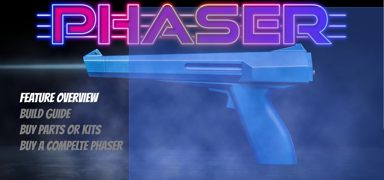



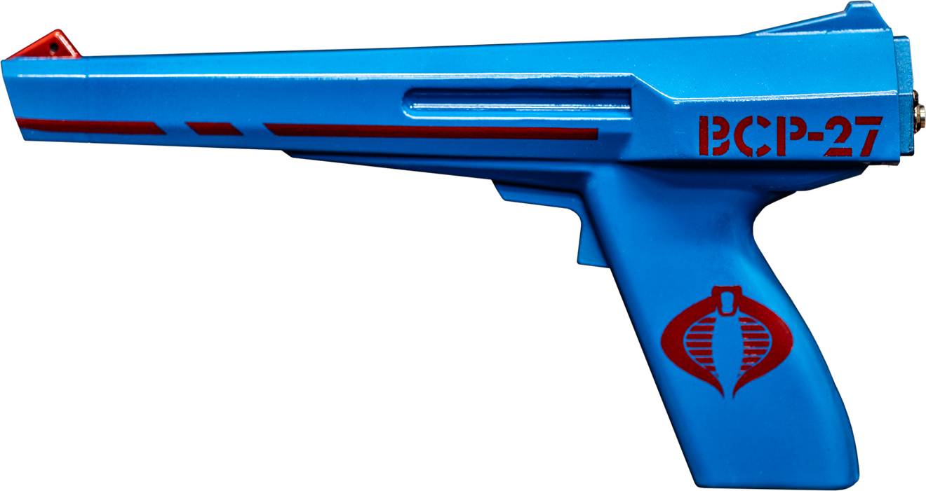


The Blamcon phaser is a blast from the past with a modern feel. The grip is designed to fit comfortably in the hand of small players while still being usable by those with larger mitts. This is the only Blamcon without solenoid support but trades this for simplicity, the only thing you need is a USB port to get in the game. There’s two ambidextrous buttons on the back with a RGB LED. This is our most maker friendly design if you’re building your own, only four parts all in!
Features:
- Trigger and A/B buttons
- Rumble
- RGB LED
- Easy USB cable only design
Use the model browser to highlight any parts and see where they fit in the Phazer.
Use the explode model to see how it fits together.
Source parts yourself or buy a complete kit (or even a ready to go Phazer), build your way! If you do build yourself the parts list below are from vendors we have used. Some links are affiliate and help support Blamcon.
Individual Parts List
Parts list for the Phazer, links are clickable and go to the last known quality vendor of that part. If a link is broken please let me know on Discord.
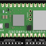 Blamcon CoreBuy
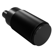 SEN0158 CameraBuy
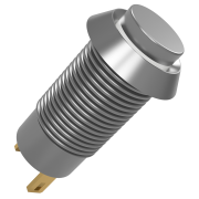 8mm ButtonBuy
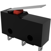 MicroswitchBuy
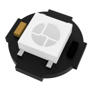 NeoPixel LEDBuy
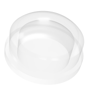 LED Diffuser (printable)Buy
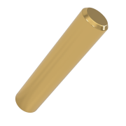 4x18mm Metal RodBuy
 4x8x.5 WasherBuy
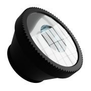 Fisheye LensBuy
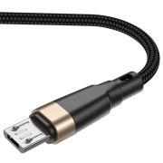 USB CableBuy
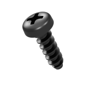 Pan Head ScrewsBuyPan Head M2.5 x 4
Pan Head M2.5×12 x 2
Pan Head M3X8
Pan Head M3X10 x5
Pan Head M3X12 x4
Pan Head M3X16
Pan Head M3X18 x2
Pan Head M3X20 x2
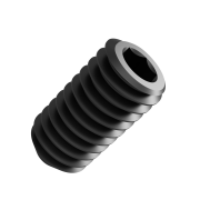 Grub Screw M3x4Buy
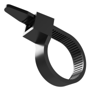 Zip Tie 2.5mm
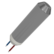 7mm Vibration Motor (with core)Buy
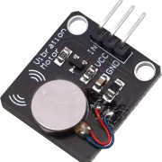 Arduino Rumble Module (no core)Buy
Tools Needed
These are the reccomended tools, I’m sure if you’re creative you can swap many of these out but these are what we use.
- #1 Phillips
- #2 Phillips Screwdriver
- 1.5mm Hex Key (optional for wide angle lens set screw)
- Soldering Iron/Solder
- Needle Nosed Pliers
- Small Chisel or ScraperUsed for cleaning up the prints
- DrillI used a hand drill, be careful with a power drill and it works fine. Use metric bits if you can: 4mm 3mm 2.5mm 2mm 1.5mm
- Hot Glue Gun
Wire Lengths
There are two sets of wire lengths: One if you’re using a Blamcon core and one if you’re using a bare Pi Pico W. Colors are just reccomended.
With Blamcon Core
Just Pi Pico W
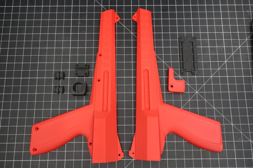
1. 3D PRINTED PARTS
PARTS
- Blamcon_Phazer_BodyRight_V1
- Blamcon_Phazer_BodyLeft_V1
- Blamcon_Phazer_Panel_V1
- Blamcon_Phazer_Trigger_V1
- Blamcon_Phazer_PlugR_V1
- Blamcon_Phazer_PlugL_V1
- Blamcon_Phazer_LensAdapter_V1
- Blamcon_Phazer_RumbleCover_V1 (Blamcon Core Only)
- Blamcon_Phazer_PicoHolder_V1 (Pico Only)
STEPS
- First determine if you’re building your Phazer using a Blamcon Core or just a Pi Pico W
- If you are not using a Blamcon Core print Blamcon_Phazer_PicoHolder_V1
- If you are using a a Blamcon Core print Blamcon_Phazer_RumbleCover_V1
- Determine if you’re using a wide angle lens or not, refer to our guide here: https://blamcon.com/get-started-with-blamcon/ir-emitters/
- Print the parts in the orientation shown, use support!
- Predrill all the holes! This is very important as the holes are slightly undersized to account for different 3D printers. M3 pan head screws cannot take a lot of torque and can break if forced.
- Screw holes that go all the way through should be drilled to 3mm (1/8in)
- Screws that do NOT go all the way through should be drilled to 2.5mm (7/64) EXCEPT FOR THE TRIGGER SWITCH AND CORE MOUNTING HOLES!!!
- Trigger switch holes should be drilled to 2mm (5/64)
- Core mounting holes should be fine. Drill to 1.75mm (1/16) if need be
- The 4mm trigger bar holes and trigger should be drilled to 4mm (5/32)
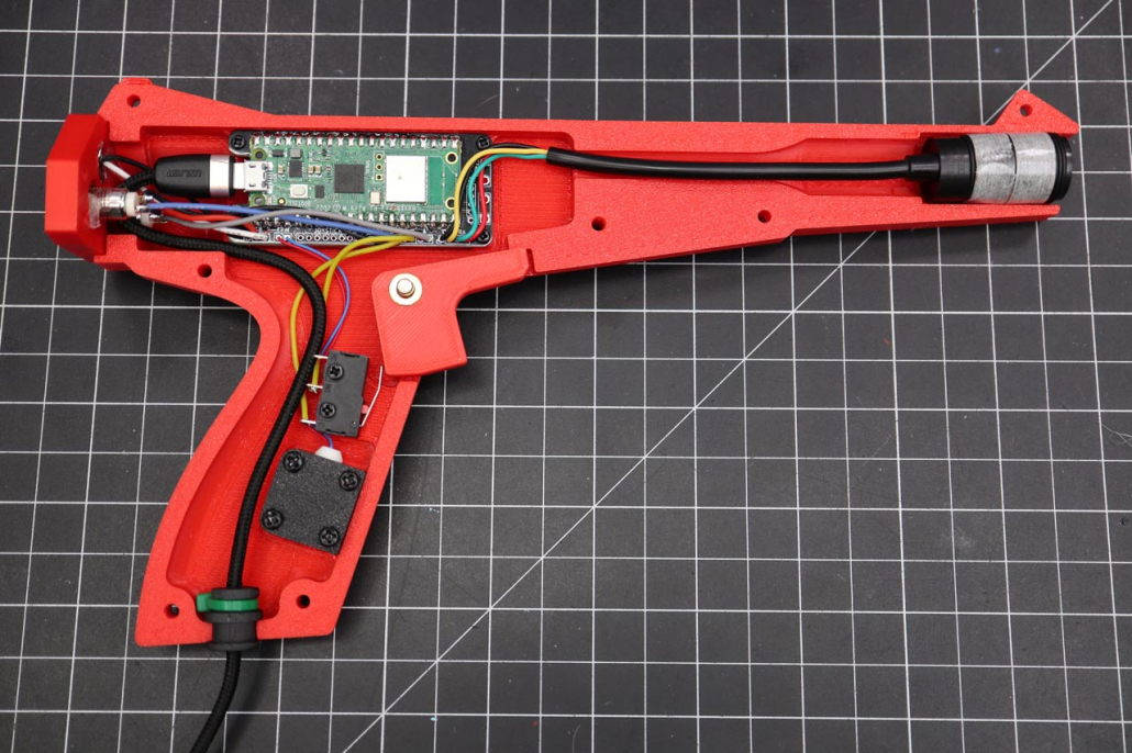
2. COMPLETE WITH CORE
This is a reference to how the completed build looks using a Blamcon Core before putting the side on. Use this as a reference to how things are going if you have any issues.
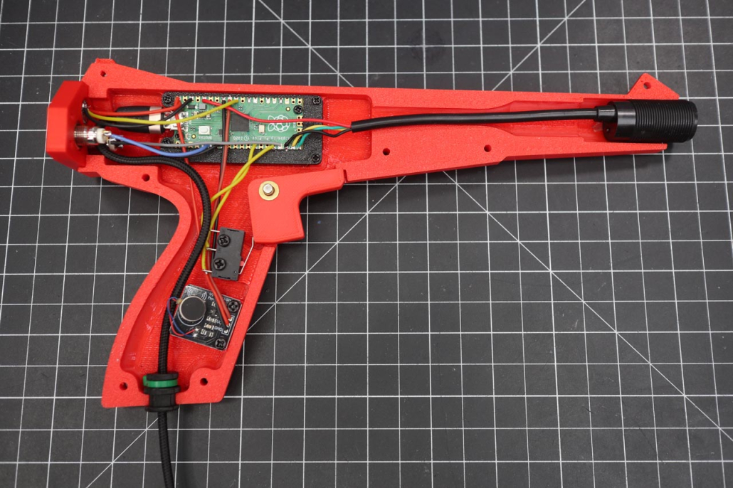
3. COMPLETE WITHOUT CORE
This is a reference to how the completed build looks using a Pi Pico W before putting the side on. Use this as a reference to how things are going if you have any issues. This build guide follows the WITH core build, if you are building without just swap the rumble motor for the arduino rumble module and use the wire lengths above. There is a more detailed pinout as the last step in this manual to help you know where to solder everything
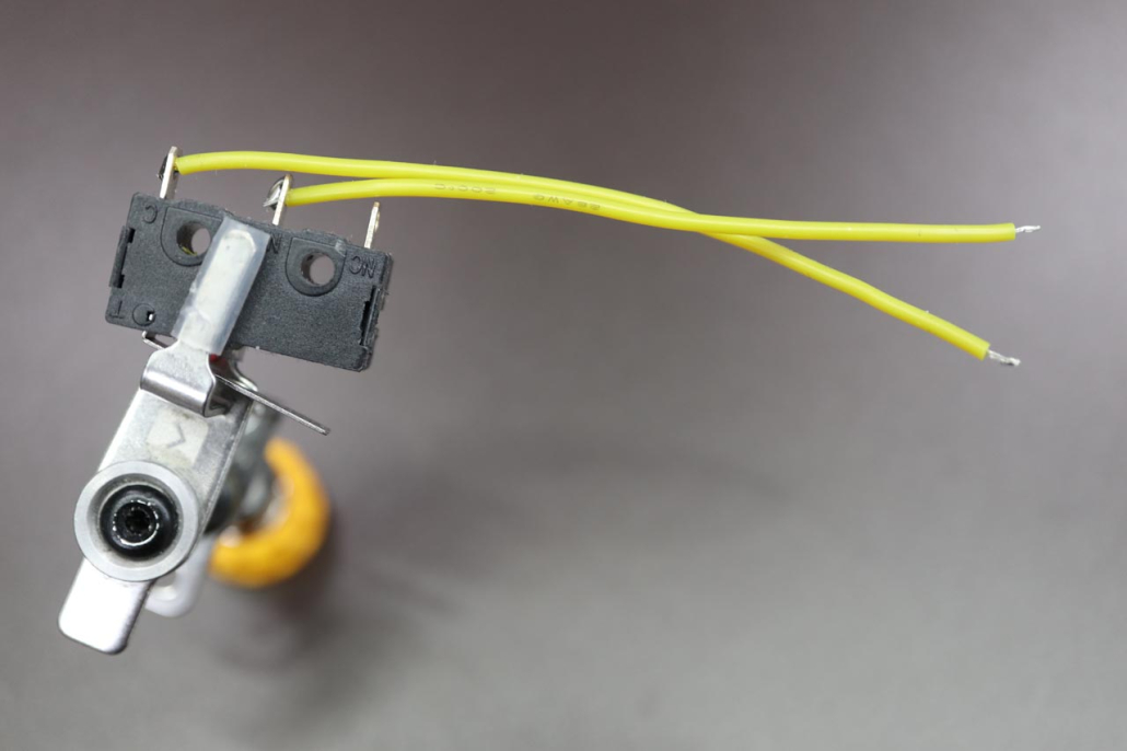
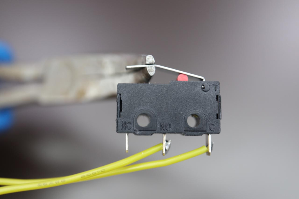
4. SOLDER THE TRIGGER
PARTS
- Microswitch
- 7cm wire
- 6cm wire
STEPS
- Solder the 7CM wire to the pin of the microswitch closest to where the metal actuator joins the body with the wire facing towards the middle. This is the common pin.
- Solder the 6CM wire to the center pin of the microswitch with the wire facing the same way as the other wire. This is the normal open pin.
5. BEND THE TRIGGER
PARTS
- Microswitch
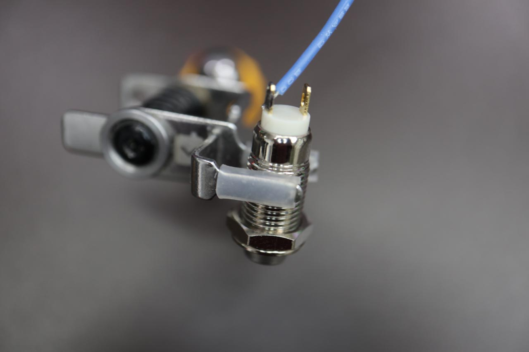
STEPS
- Give the tip of the microswitch a small bend. It should be able to actuate easily, it’s just a teeny bend don’t overdo it.
6. SOLDER THE B BUTTON
PARTS
- 8mm button
- 5cm wire
STEPS
- Solder the wire to either pole with the wire going towards the middle
- Some of these switches are sensitive to heat, do not apply heat for a long time, should go very quick
Note: The next 3 steps cover bridging the ground wire between the two buttons so they can share one ground. Look ahead. If you find this hard you can just use a second 5cm wire here and use 2 6.5cm wires in the next step and just solder each to their own ground. I like bridging, that’s me, you do what’s easiest for you.
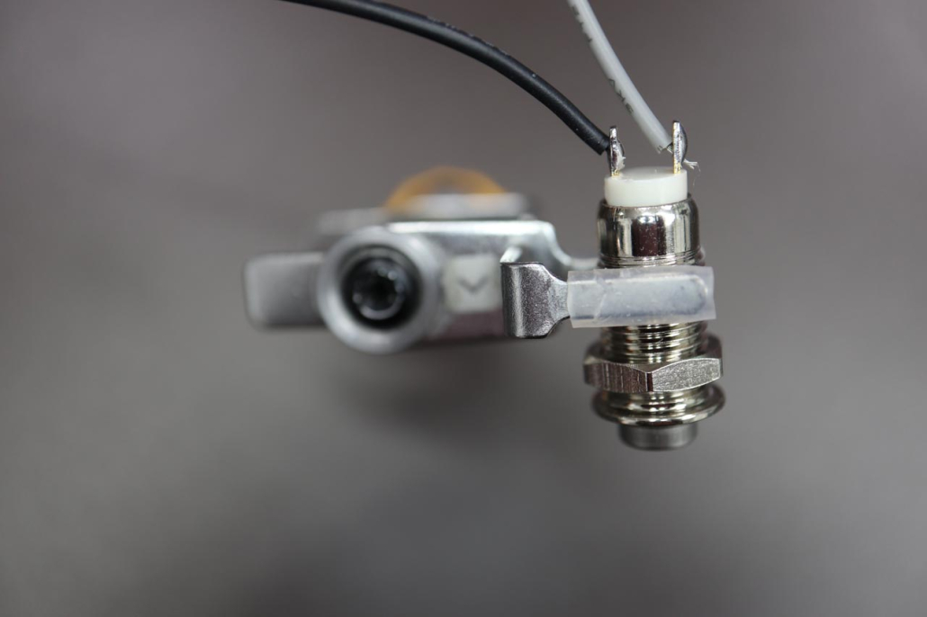
7. SOLDER THE A BUTTON
PARTS
- 8mm button
- 8cm wire
- 6.5cm wire
STEPS
- Solder the 8cm wire to either pole with the wire facing outwards
- Solder the 6.5cm wire to either pole with the wire facing inwards
- Some of these switches are sensitive to heat, do not apply heat for a long time, should go very quick
8. INSTALL THE A/B BUTTONS
PARTS
- Presoldered A button
- Presoldered B button
- Blamcon_Phazer_Panel_V1
STEPS
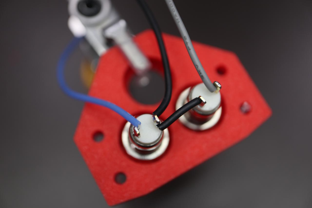
- Install the A/B buttons into Blamcon_Phazer_Panel_V1 by screwing them in. Orient the buttons as shown with the longer ground wire on one button facing towards the pole your haven’t soldered on the other button. Use the tip of a knife to get the nut tight.
- Optionally add a drop of hot glue to secure the buttons from coming loose over time.
- Point the ground wire to the bare pole on the other button, use a sharp knife to make a nick in the wire and pull the insulation up enough to wrap it half way around the pole (horseshoe). Solder the ground wire onto the other button so they both share one ground wire..
Note: if you are using a thick USB Cable you may want to do step 22/24 and thread the USB cable through before doing the bridge. If you are using a kit you’re fine if not check those steps first and use your best judgement.
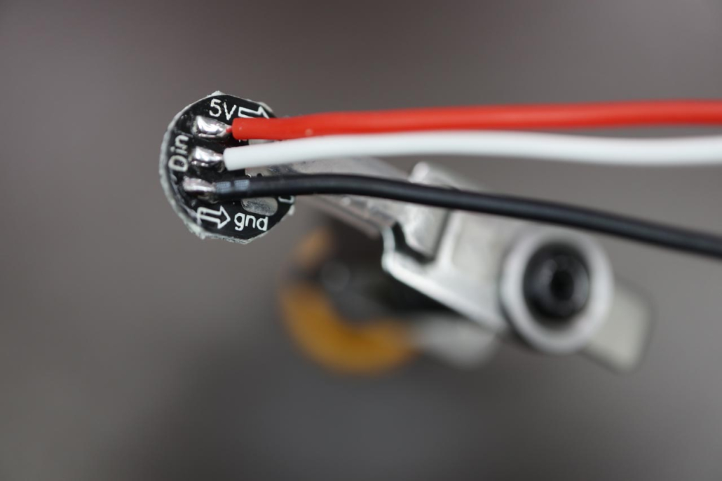
9. SOLDER THE LED
PARTS
- 3X 5CM wires
STEPS
- Solder the wires to the LED as shown, make sure they’re on the same side as shown with the arrows on the LED PCB pointing away.
- The best way to solder these is to ‘tin’ the LED by adding a bit of solder to the 3 poles first. Then tin the 3 wires by adding a bit of solder to them. Finally touch the tinned wire to the tinned LED pad and heat, it should melt together easily.
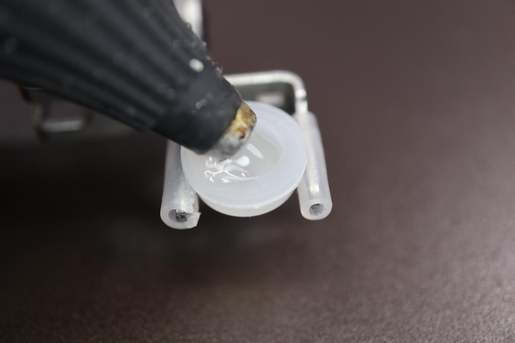
10. GLUE THE LED INTO THE DIFFUSER
PARTS
- LED Diffuser
STEPS
- Add hot glue to the LED diffuser until it is full then insert the LED while it’s still hot. Wear gloves as you may burn yourself.
- Trim off any excess glue or pull it off with your gloved hand while still hot.
Note that this is also 3D printable part if you don’t have a diffuser.
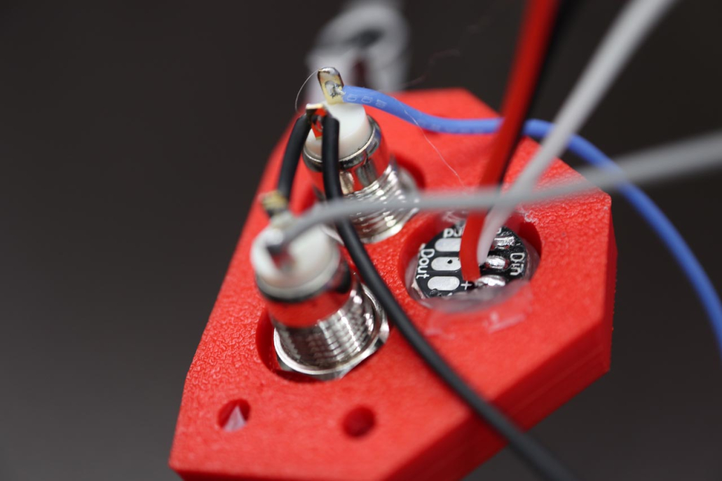
11. INSTALL THE LED
PARTS
- Presoldered LED with diffuser glued on.
STEPS
- Insert the LED into the hole until it protrudes out the back. This should be a firm fit, trim the hole if it’s too tight.
- Optional: use a small drop of hot glue on the back at both sides to hold it in place.
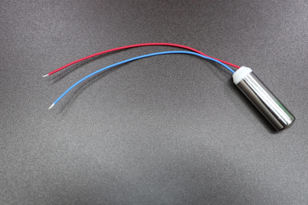
12. TRIM THE RUMBLE MOTOR WIRES
PARTS
- 7mm rumble motor
STEPS
- Trim the rumble motor wires to 7cm and strip the ends for soldering
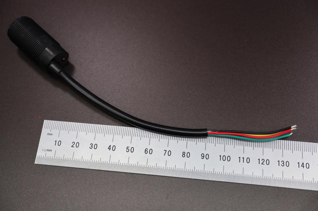
13. PREPARE THE CAMERA
PARTS
- IR Positioning camera
STEPS
- Cut the camera wire to 14CM from where it comes out from the camera. START FROM THE END OF THE WIRE PROTECTOR NOT FROM THE BODY (the cone)
- Trim the insulation off the camera 9cm down from the end of the core by scoring it then breaking it off and sliding
- Do not cut too deep as you will cut the wires under, scoring it is enough then bending to create a break
- When pulling do not use the camera as a leverage point or you can break the wires inside, pull from both ends of the insulation and it will come off just fine
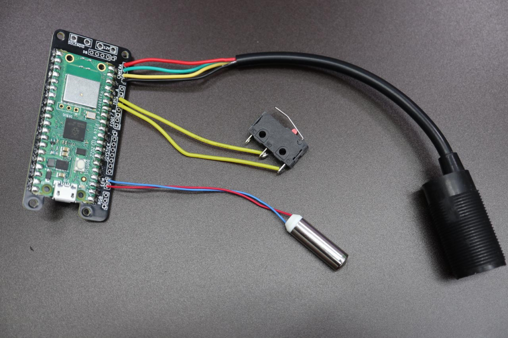
14. SOLDER THE CAMERA/TRIGGER/RUMBLE
PARTS
- Prepared IR positional camera
- Prepared rumble motor
- Soldered trigger switch
STEPS
- Solder the rumble motor on as shown
- Ground to square
- Positive next (middle)
- Signal on the other end
- Solder the IR positional camera
- Ground to square
- Yellow beside ground
- Green next
- Red at the top
- Solder the rumble motor
- Orientation doesn’t matter but if you want to be pedantic blue to the square pad
Note: If you are using just a Pi Pico W see the pinout at the end for what goes where
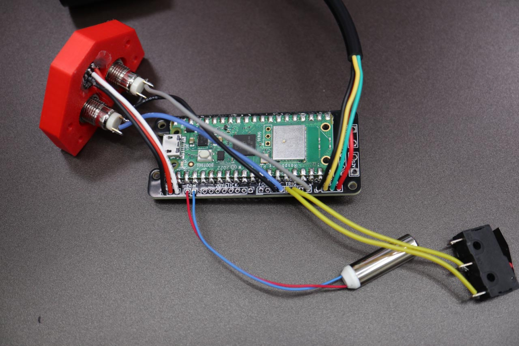
15. SOLDER THE A/B/LED
PARTS
- Complete back panel with A/B/LED installed and soldered
STEPS
- Solder the LED as shown
- Ground to square
- Positive next (middle)
- Signal on the other end
- Solder A button
- To the circle hole on the B connector on the core
- Solder B button
- Solder the signal wire to the circle hole on the B connector on the core
- Solder the daisy changed ground wire to the square hole onthe B connector on the core
Note: If you are not daisy chaining you will have 2 wires to each button, doesn’t matter which goes to which so long as the 2 A wires go to A and 2 B wires go to B
Note: If you are using just a Pi Pico W see the pinout at the end for what goes where.
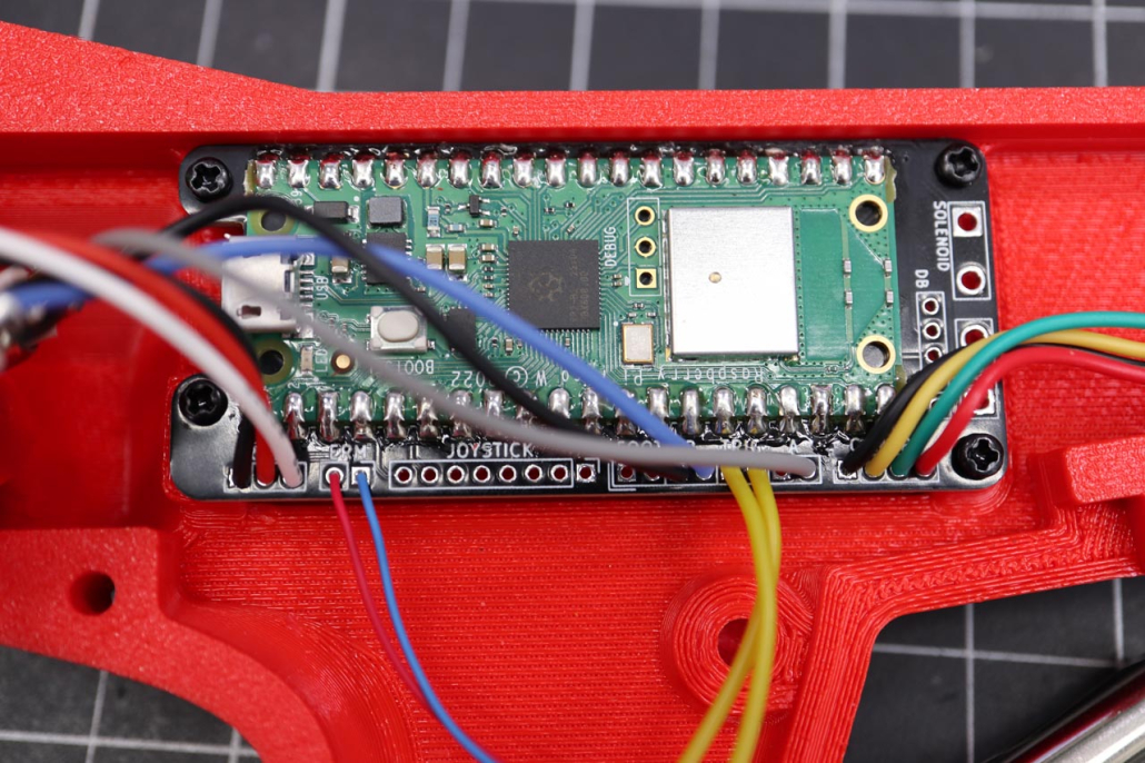
16. INSTALL THE CORE
PARTS
- M2.5x5mm Pan Head Screw X4
- Soldered Blamcon core
STEPS
- Screw the Blamcon core in as follows, do not overtighten as these are small screws
- If you do strip them, fill the hole with glue and redrill, no biggie
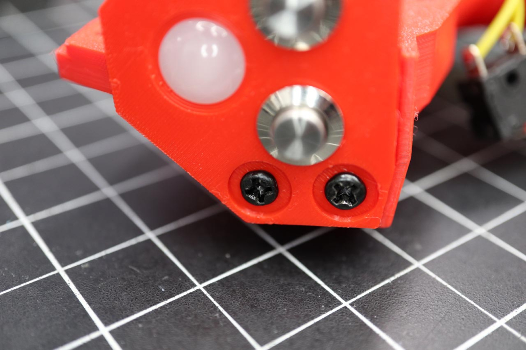
17. SCREW ON THE BACK PLATE
PARTS
- M3x12mm Pan Head Screw X2
- Finished back panel
STEPS
- Screw the panel onto the frame
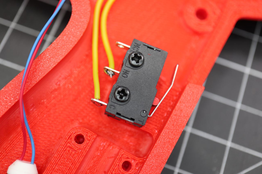
18. SCREW IN THE TRIGGER SWITCH
PARTS
- M2.5×12 Pan Head Screw X2
- Trigger switch
STEPS
- Screw the trigger switch in as shown
Note: Some switches, like Omron, are undersized on one side. Make SURE you drill the holes to 2.5mm or they can crack!
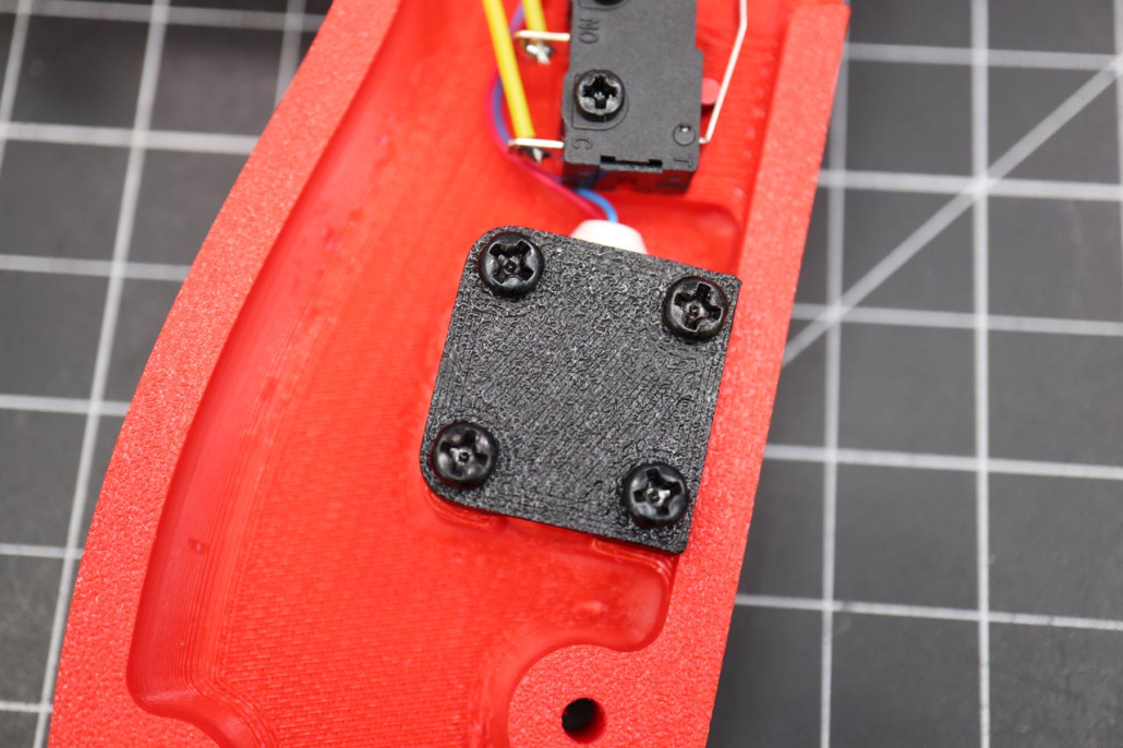
19. SCREW IN THE RUMBLE
PARTS
- M3x10mm Pan Head Screw x 4
- Blamcon_Phazer_RumbleCover_V1
STEPS
- Screw the rumble cover on as shown, the rumble should be snug and not rattle around. If it’s loose add a bit of tape to the rumble for a better fit.
Note: If you are using the Arduino rumble module screw it on with 2 M3x10mm Pan Head Screws as shown in step 3
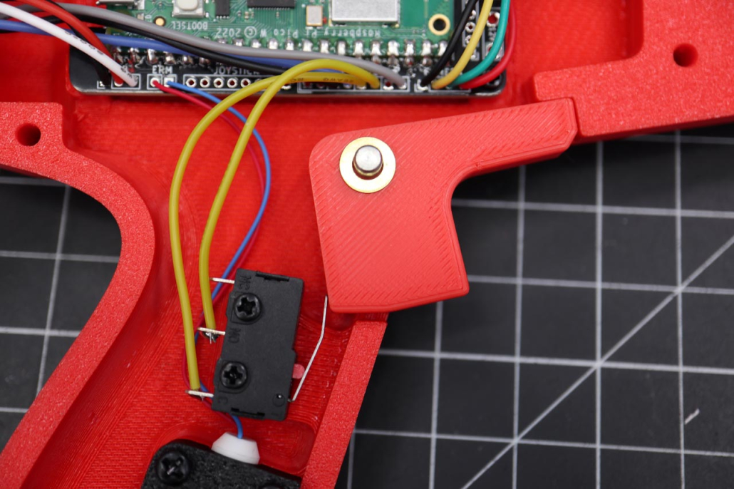
20. INSTALL THE TRIGGER
PARTS
- M4x19mm Metal Bar
- 4mm washers X2
- Blamcon_Phazer_Trigger_V1
STEPS
- Make sure the trigger moves freely on the bar, size it with a drill bit or knife until it spins freely or you will get a sticky trigger
- Place the the metal bar in the hole in the frame, add a washer onto one side
- Place the trigger on the bar with the second washer on the other side
21. INSTALL THE CAMERA
PARTS
- IR Positional Camera
- Double sided tape
STEPS
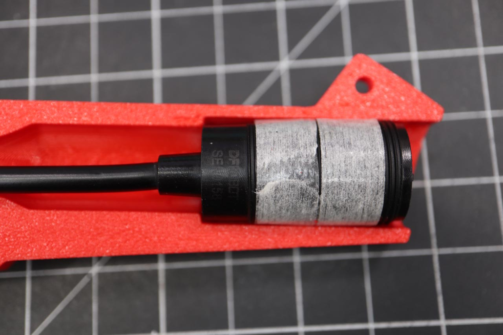
- Place a few wraps of double sided tape on to hold it in place. I recommend 10mm craft tape, it’s cheap and thin
- If you are using the wide angle lens make sure you are leaving enough space to thread the adapter on. I use only one wrap of 10mm tape on the back if I’m using the adapter. In the picture you see me using two but see step 25 for how it looks with one.
22. TRIM THE USB CONNECTOR (IF NEEDED)
PARTS
- USB cable
STEPS
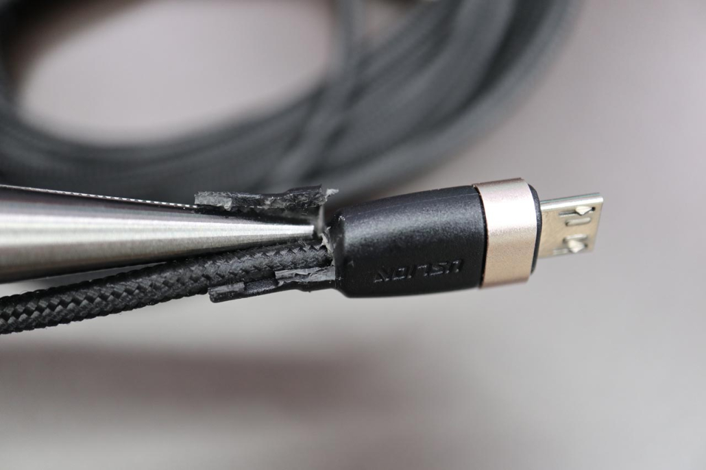
- Some USB cables have a long cable protector on the back, this can be easily removed by cutting into the cable protector and then peeling it off with pliers.
23. THREAD THE USB CABLE (IF NEEDED)
PARTS
- Back panel
- USB cable
STEPS
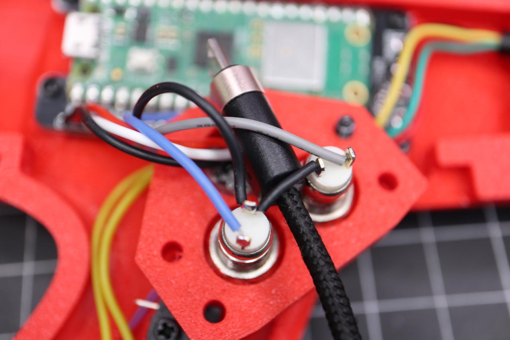
- Remove the back panel screws so it’s free
- Thread the USB connector between the two switches under the bridged ground wire
24. INSTALL THE CABLE STOPPER
PARTS
- 2.5mm Zip Tie
- Blamcon_Phazer_PlugR_V1
- Blamcon_Phazer_PlugL_V1
STEPS
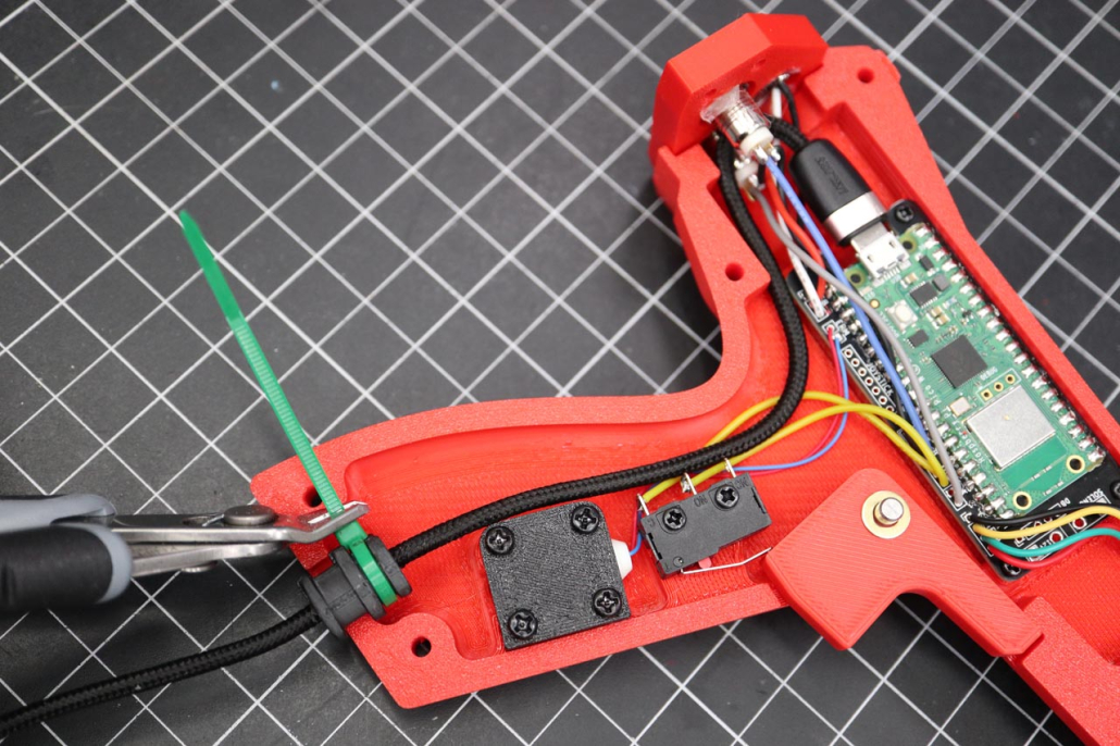
- Place the zip tie loosely around the USB cable with one click so it stays on
- Place the USB cable as shown, make sure it’s not going to get caught in the frame
- Place the plug halves in the position shown and tighten the zip tie around the plug. Note there’s a gap on one side of the plug for the zip tie head
- Crank it down! It should be firmly on with no gap, it should not move
- Cut the end of the zip tie off
Note: You don’t HAVE to use zip tie, a little hot glue does the trick. I like the zip tie being removable and adjustable and an easy way to mount, but it is optional
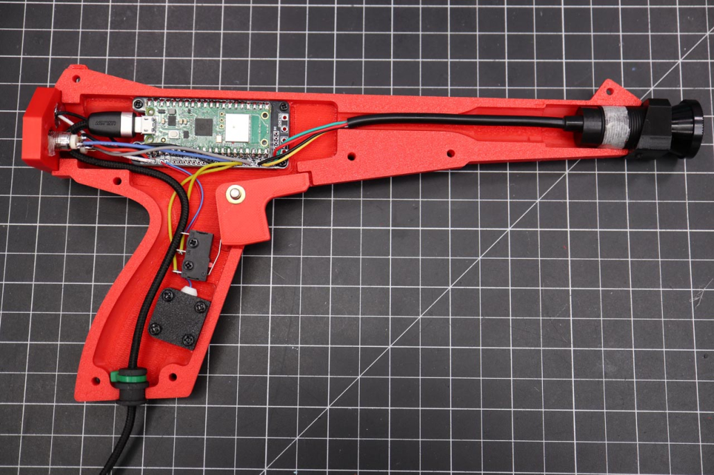
25. COMPLETED INTERNALS
STEPS
- This is the best time to algin the camera. Follow the instructions in this video: https://www.youtube.com/watch?v=QJ2YZrbyOsE&t=4018s
- Check everything carefully! It should look exactly like the image
Note: This is shown with the wide angle lens installed, you may or may not need it.
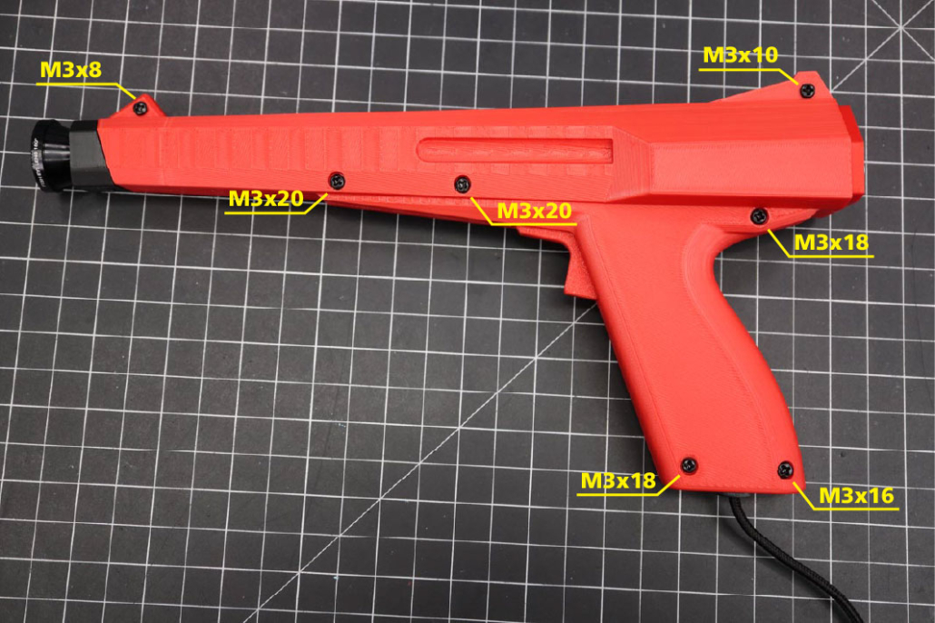
26. SCREW IT TOGETHER
PARTS
- M3x8mm Pan Head Screw
- M3x10mm Pan Head Screw
- M3x16mm Pan Head Screw
- M3x18mm Pan Head Screw x 2
- M3x20mm Pan Head Screw x 2
- Printed Phazer_BodyRight_V1.STL
STEPS
- Firmly secure the Frame together.
- 8mm screw is for the front sight
- 10mm for the rear
- 18mm is for the front of the grip, and 16mm is for the back
- The 2 20mm screws on the front of the frame and the 18mm on the back
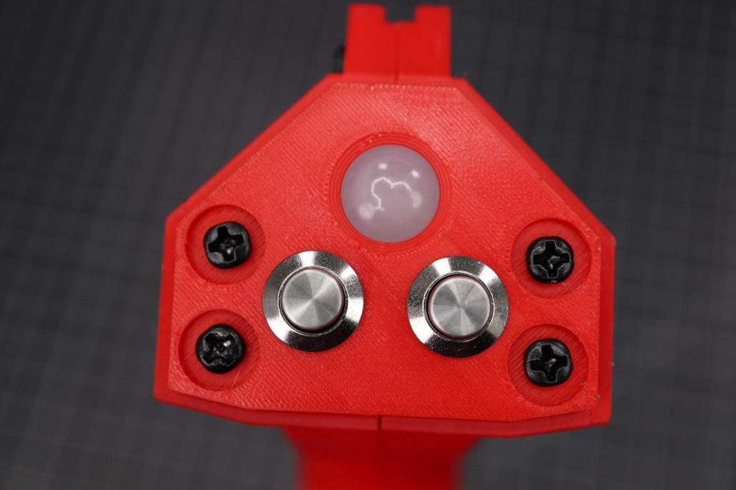
27. SCREW ON THE BACK PLATE
PARTS
- M3x12mm Pan Head Screw X2
STEPS
- Screw the last two screws on
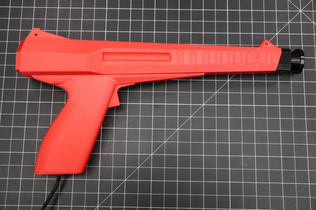
28. GO HAVE SOME FUN!!
Your Blamcon Phazer is complete! Time to have some fun. We have a free game on Steam, Blamcon Shooting Gallery, you can try your new Blamcon out with.
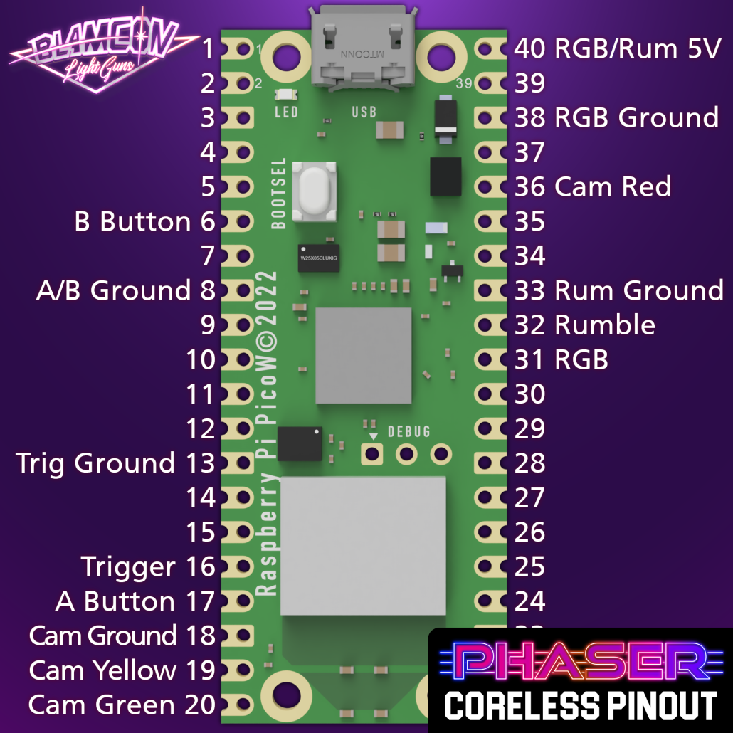
29. NO CORE PINOUT
If you are not using a Blamcon Core this is a clearer reference to the wiring.
The M3F files are in the correct print orientation and organized by tray. They will open in Orca Slicer as trays you can slice with your own settings and printer.
The Gcode files are ready to print for the printers listed, they are set up for PLA at .16. They print slow and strong and these are the same print settings we use. We print with Matter3D Performance PLA but should work with any decent PLA, print at your own risk.
All Blamcon models are released under the Creative Commons – Attribution – Non-Commercial – No Derivatives license. By downloading models from Props3D you are agreeing to abide by these terms.