







The Aliens Extermination Arcade Gun is a pedestal mounted gyro gun, normally something you couldn’t use by itself. The Blamcon conversion frees it from its shackles and allows you to play like you should. Working ammo counter, solenoid recoil, rumble, this is a full featured light gun. You don’t need anything but the 2 part outside shell to convert this.
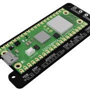 Blamcon CoreBuy
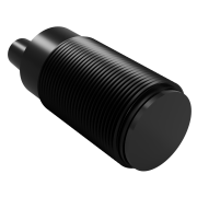 SEN0158 CameraBuy
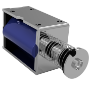 JF-Z05 SolenoidBuy
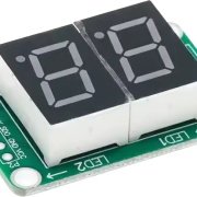 74HC595 Red 2 Segment CounterBuy(OR LED see below)
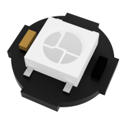 Neopixel LEDBuy(OR Counter see above)
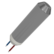 7mm Vibration MotorBuy
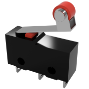 Roller MicroswitchBuy
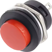 16mm Push Button X 2Buy
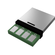 USB ConnectorBuy
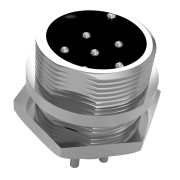 GX-16 6 Pin MaleBuy
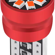 12V T10 W5W Red LEDBuyFire Effects (Optional)
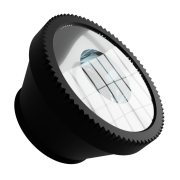 Fisheye LensBuy
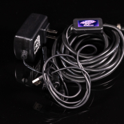 6 Pin Cable and 12V adapterBuy
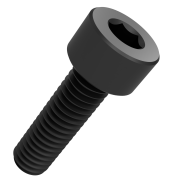 Cap head M2.5x12BuyTrigger
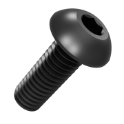 Button Head M4x6 X 4BuySolenoid to Mount
- Button Head M4x16BuyBody Barrel
- Button Head M4x25 X 11BuyBody
- Button Head M4x30 (Optional)BuyOrange Tip
 Pan Head M2x5 X 2BuyCore to Mount
- Pan Head M3X6 X 4BuyCounter Holder
- Pan Head M3X10 X 4BuyRumble Motor Mount
- Pan Head M4X10BuyCore Mount Holder
- Pan Head M4X16 X 4BuySolenoid Mount
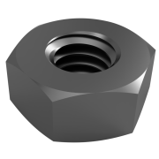 M4 Nut X 12Buy
Wire Lengths
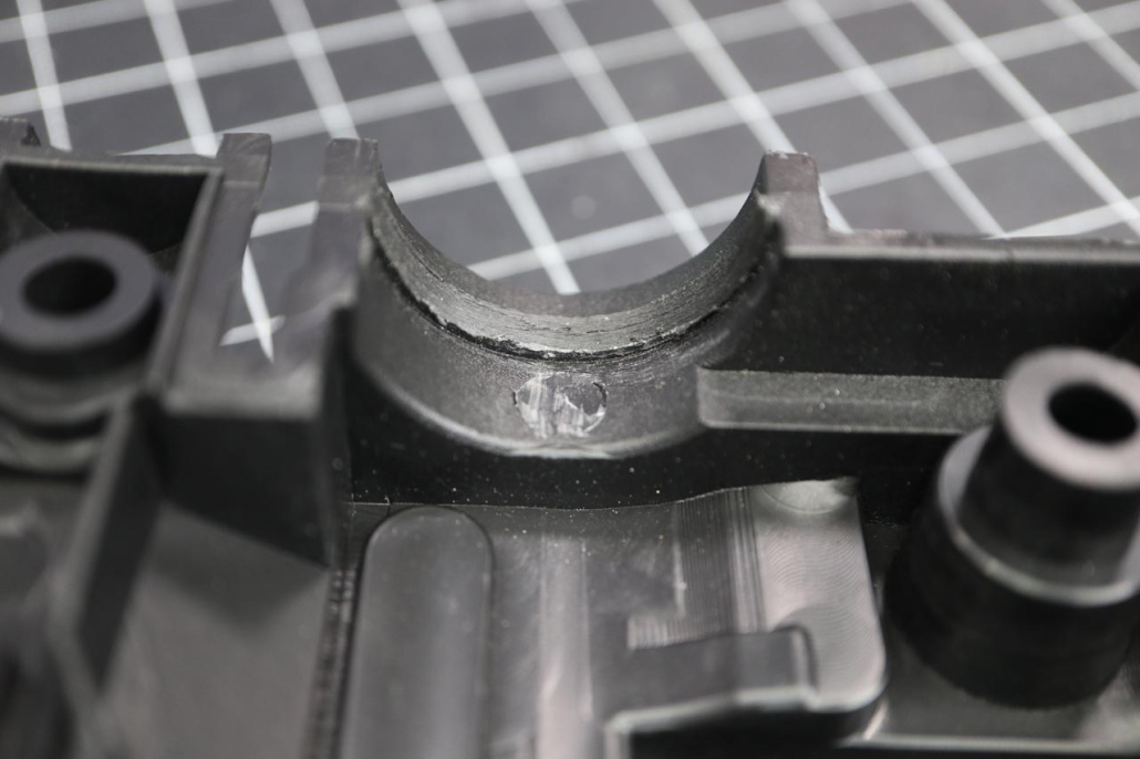
1 Cut the Camera Opening
- Using side cutters cut the posts on the inside of the grenade launcher hole
- Using side cutters cut most of the grenade launcher hole, going no closer than 3mm (1/8in)
- With a Dremil cut the opening to shape, leave about 1.5mm (1/16), the width of the 3D printed camera holder lip
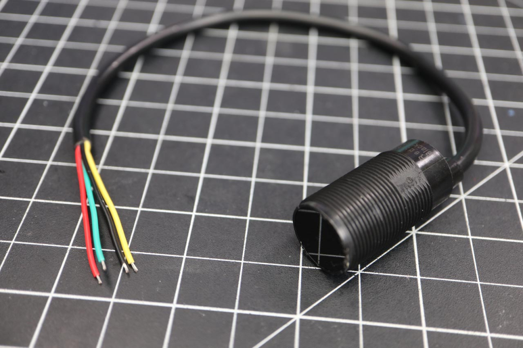
2 Prepare the Camera
PARTS
- SEN0185 Camera
STEPS
- From the point the wire comes out of the camera (the cone), measure 23cm and cut to length
- Cut back the outer insulation by scoring it 3CM down from the cut you just made and rocking it to break it off, do this to avoid cutting into the inner wires
- Strip the tips off the 4 inner wires so the final camera looks like the picture
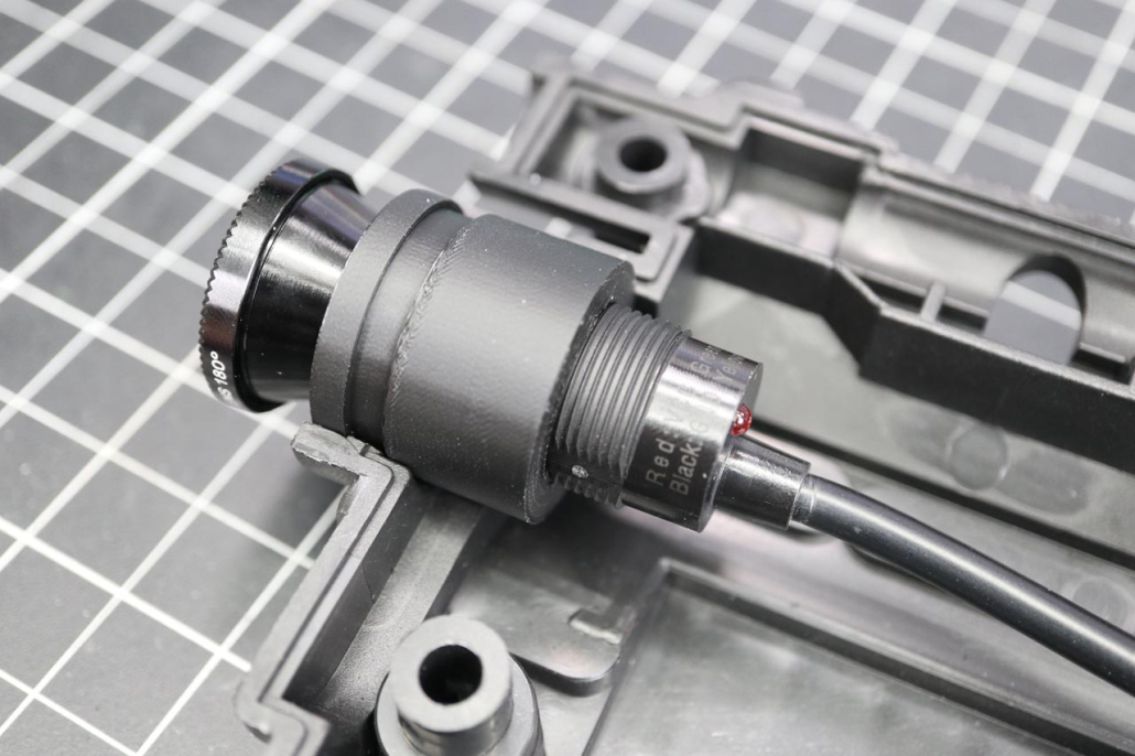
3 Install the Camera
PARTS
- Prepared SEN0158 Camera
- Wide Angle Lens
- 3D Printed Part: Blamcon_AliensArcade_CameraLensHolder_V1
STEPS
- Screw the wide angle lens into the camera holder as far as it will go, starting from the end closest to the ring on the holder. Be careful the thread pitch is only .75mm so be careful to not cross thread
- Screw the camera into the other end of the camera holder until it’s flush against the wide angle lens
- Align the camera so the cable is facing right and the LED is facing left and insert it into the hole you cut in the grenade launcher
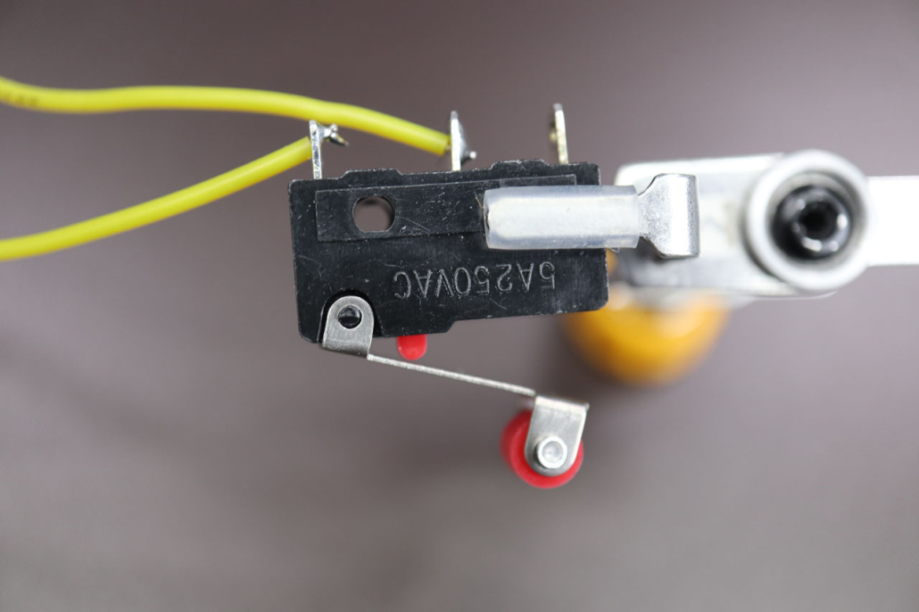
4 Solder the Trigger
PARTS
- 190mm Wire X2
- Roller Microswitch
STEPS
- Solder the first wire to the common pin facing out. The common pin is the one closest to where the metal leaf connects to the switch body
- Solder the second wire to the normal open pin in the middle. The wire faces towards the other one so they’re both facing the same direction
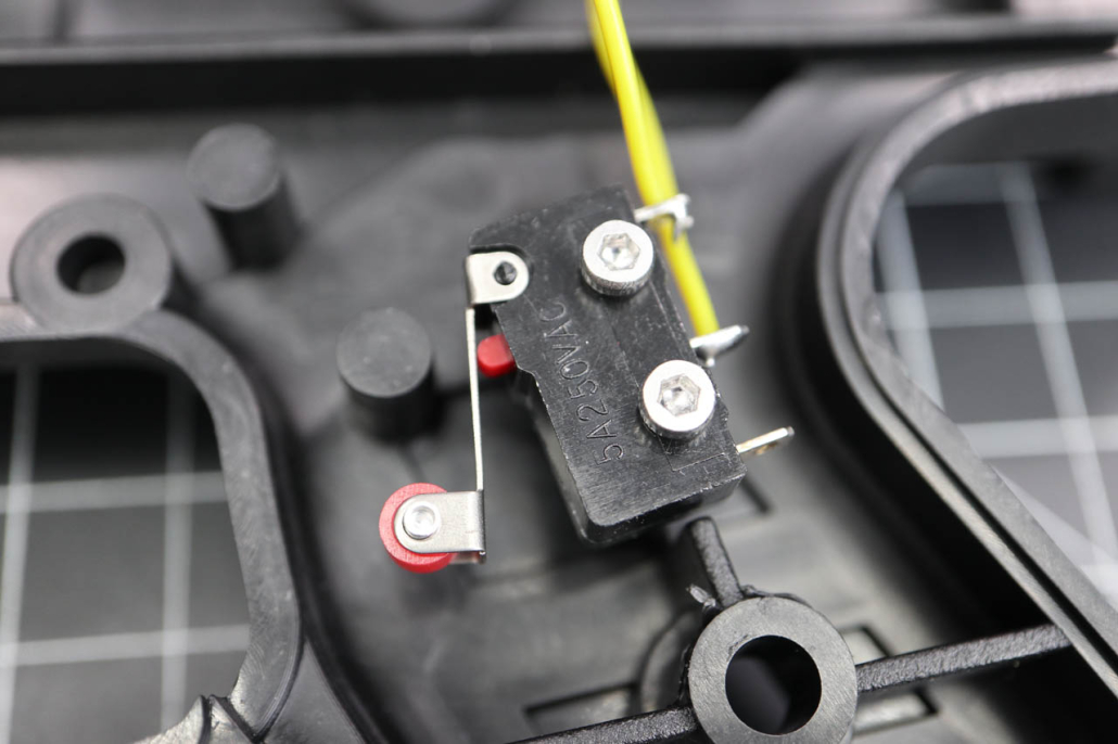
5 Install the Trigger
PARTS
- Presoldered trigger switch
- Cap head screws M2.5 x 12 X 2
STEPS
- Some roller microswitches have holes slightly less than 2.5mm, test the screws and if they’re too small drill the switch holes out with a 2.5mm drill bit.
- Screw the trigger switch in place with the roller facing down
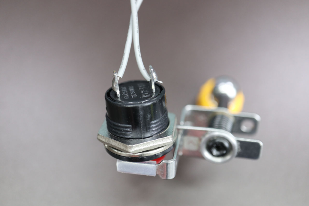
6 Solder the A Button
PARTS
- 225mm Wire X 2
- 16mm Push Button
STEPS
- Solder the wires onto the button, direction and polarity don’t matter
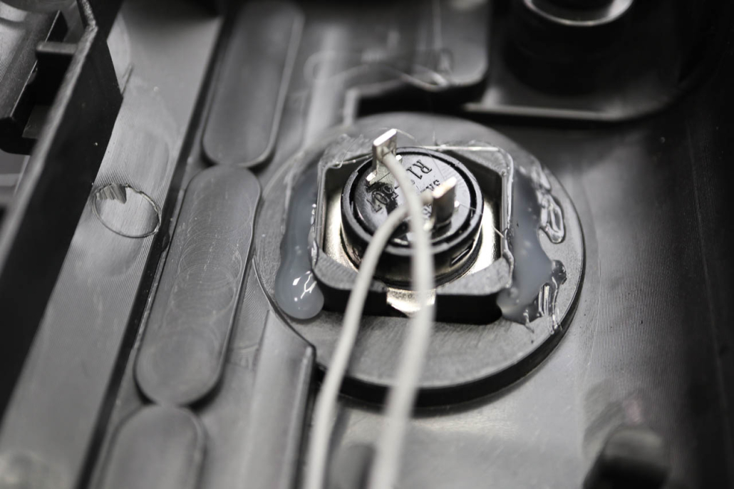
7 Install the A Button
PARTS
- Presoldered A Button
- 3D Printed Part: Blamcon_AliensArcade_ButtonA_V1
STEPS
- Put the nut in the nut holder in the back of the button
- Screw the button in tightly by rotating the button until it’s snug
- Put the button holder in the hole and glue in place with a glue gun. You don’t need a lot of glue
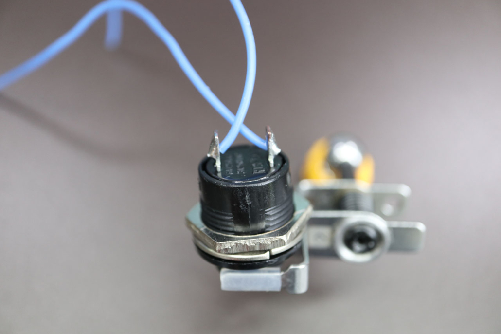
8 Solder the B Button
PARTS
- 110mm wire X 2
- 16mm Push Button
STEPS
- Solder the wires onto the button, direction and polarity don’t matter
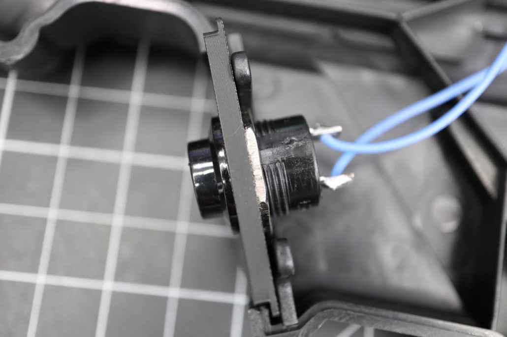
9 Install the B Button
PARTS
- Presoldered B Button
- 3D Printed Part: Blamcon_AliensArcade_ButtonB_V1
STEPS
- Put the nut in the nut holder in the back of the button
- Screw the button in tightly by rotating the button until it’s snug
- Slide the button assembly unto the slot in the gun as shown
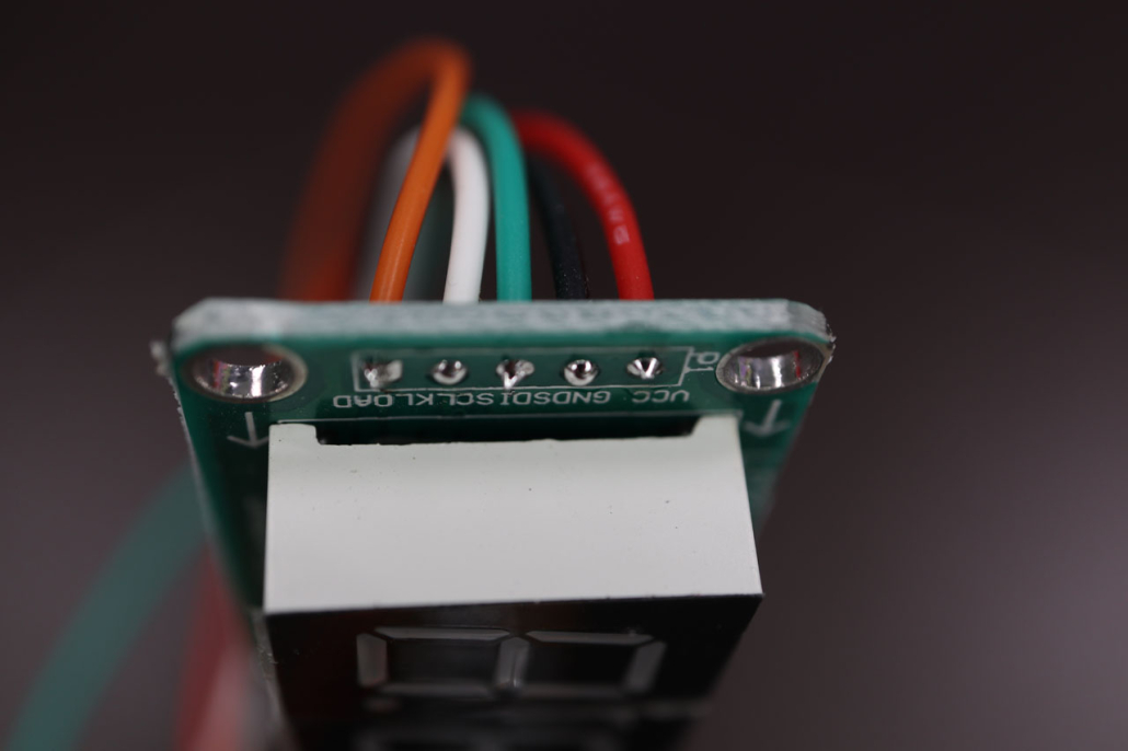
10A Solder the Counter
PARTS
- 74HC595 Red 2 Seg
- 250mm wires X 5
STEPS
- Solder one wire to each hole with the wires facing backwards away from the digits
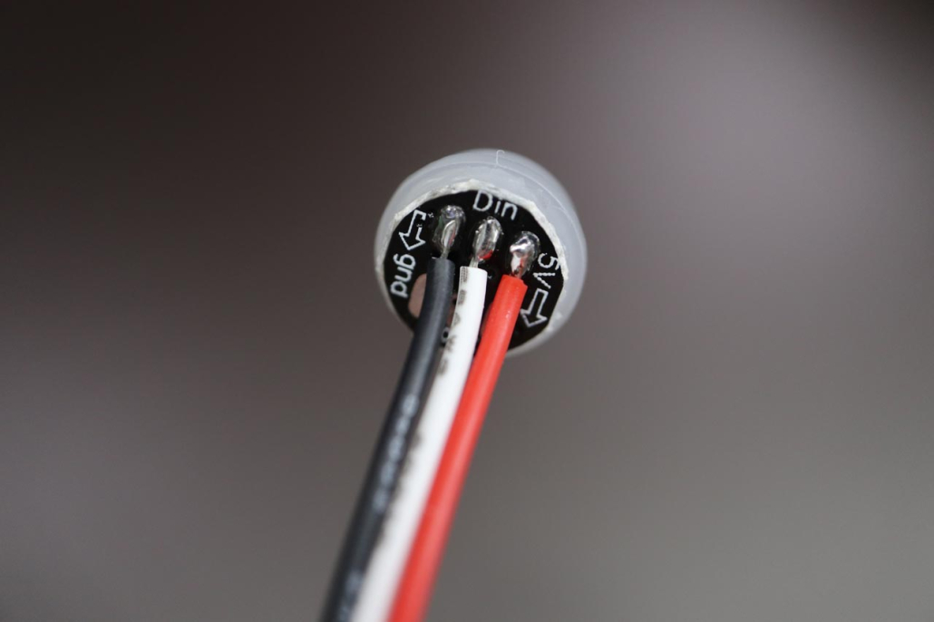
10B Solder the LED
PARTS
- Neopixel LED
- 10mm Diffuser (bought or 3D printed)
- 250mm wire X3
STEPS
- Solder the LED wires as shown
- Red to Positive
- White to Signal
- Black to Ground
- Note that the diffuser is held onto the LED by hot glue, this is predone in kits but if you’re building yourself there’s a diffuser 3D model if you need it.
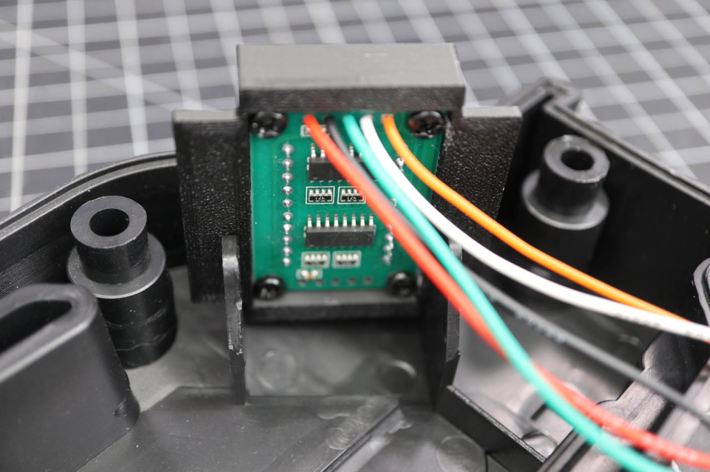
11A Install the Counter
PARTS
- Presoldered Counter
- 3D Printed Part: Blamcon_AliensArcade_AmmoCounter_V1
- Pan Head M3X6 X 4
STEPS
- Insert the counter into the holder and screw it in place with the 4 M3X6 pan head screws
- Slide the ammo counter holder into the shell, it should fit snugly
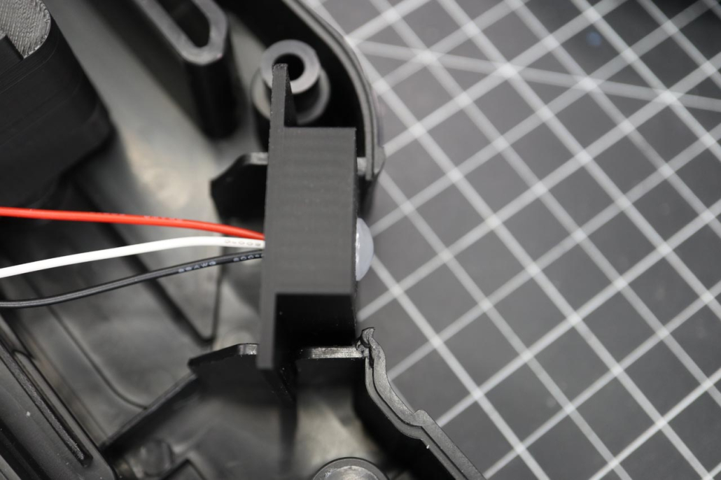
11B Install the LED
PARTS
- Presoldered LED Module
- 3D Printed Part: Blamcon_AliensArcade_LEDHolder_V1
STEPS
- Insert the LED into the holder, it should be very tight and you may have to push it in place with a dowel. If it is loose you can add a drop of hot glue after you insert it to hold it in place
- Slide the ammo counter holder into the shell, it should fit snugly
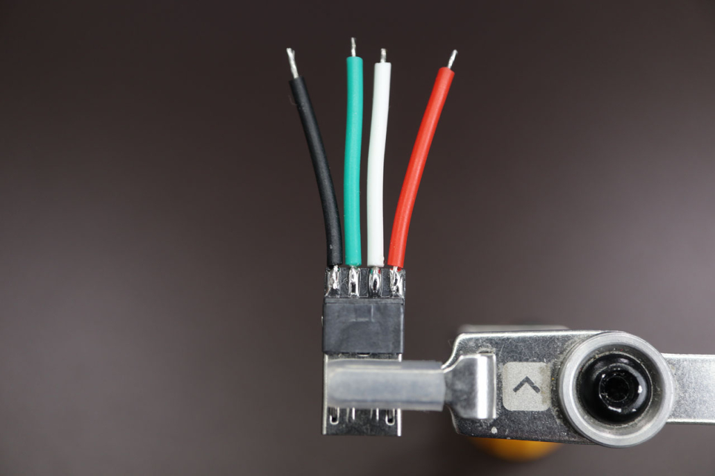
12 Solder the USB
PARTS
- Micro USB Connector
- 22mm wire X4
STEPS
- Tin the USB connector by adding a small amount of solder to each pad
- Tin the wires by adding a small amount to the end of each
- Touch the tinned pad and wire together and add heat to solder them together
- With the pads facing you and USB facing towards you, starting from the left: Black, Green, White, Red
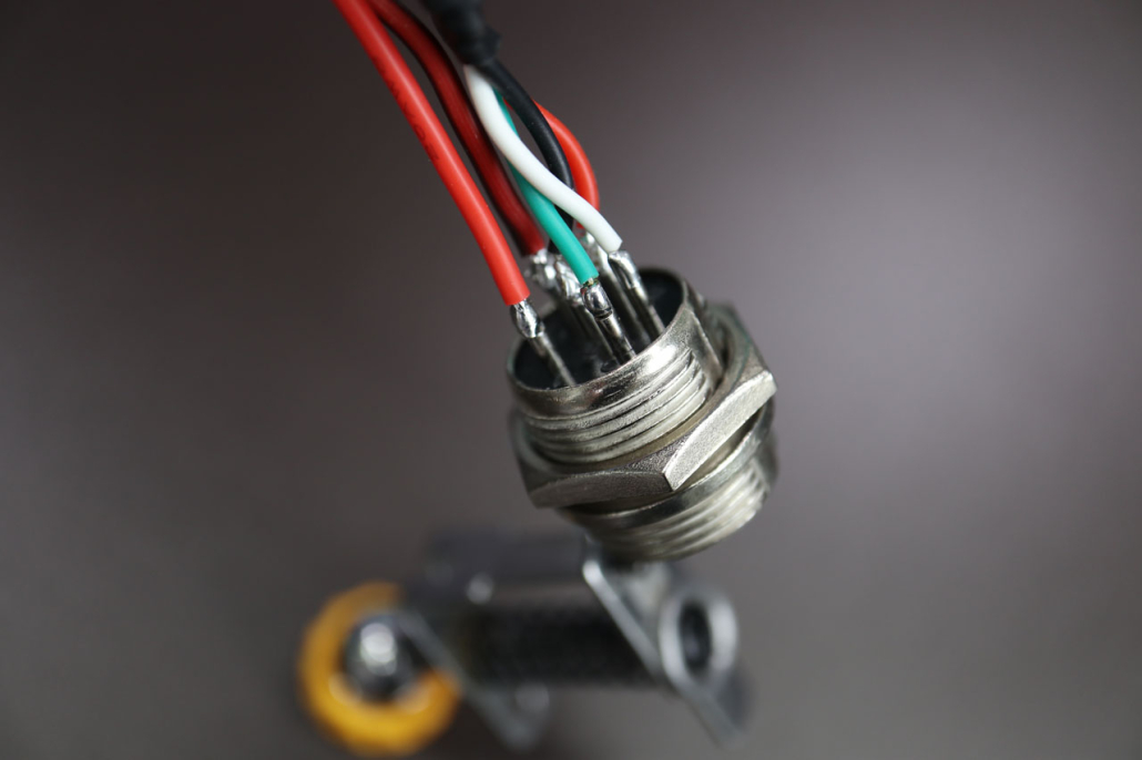
13 Solder the GX16
PARTS
- Presoldered USB Connector
- GX16-6 Male connector
- 90mm 22GA wire (2 strand)
STEPS
- Tin the GX16 Connector by heating it and adding solder to each post, filling in the ‘U’ shape
- Tin the wires by adding a small amount to the end of each
- Touch the tinned post and wire together and add heat to solder them together in the following sequence, the GX16 is numbered
- 12V Power, 22ga Red
- 12V Negative, 22ga Black
- USB Power, USB Red
- USB Data -, USB Green
- USB Data+, USB White
- USB Negative, USB Black
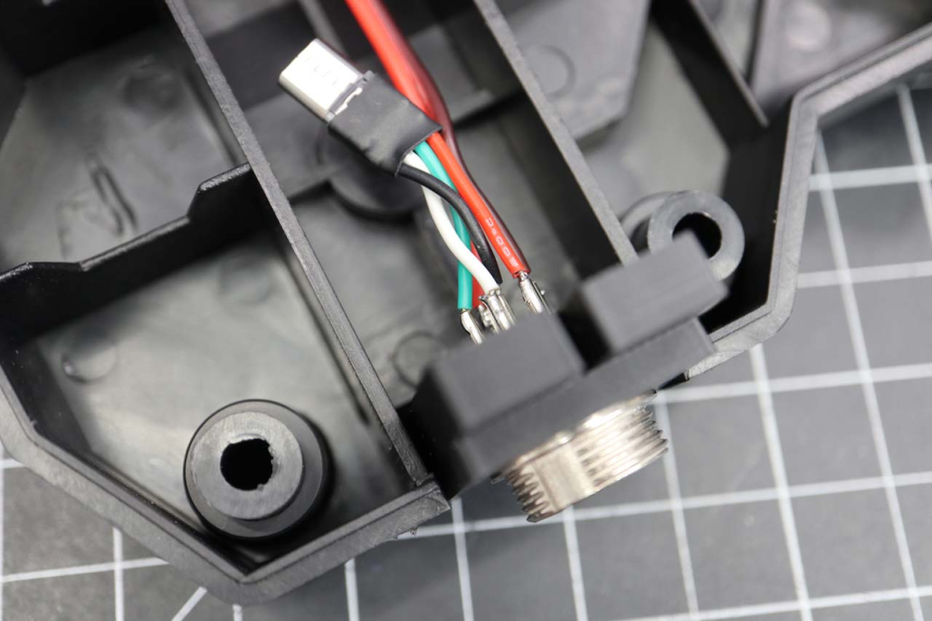
14 Install the GX16
PARTS
- Presoldered GX16 with USB
- 3D Printed Part: Blamcon_AliensArcade_GX16_V1
STEPS
- Insert the but into the nut space on the inside of the holder
- Screw the GX16 into the holder from the bottom, it should tighten on the nut
- Insert the holder into the slot on the gun as shown
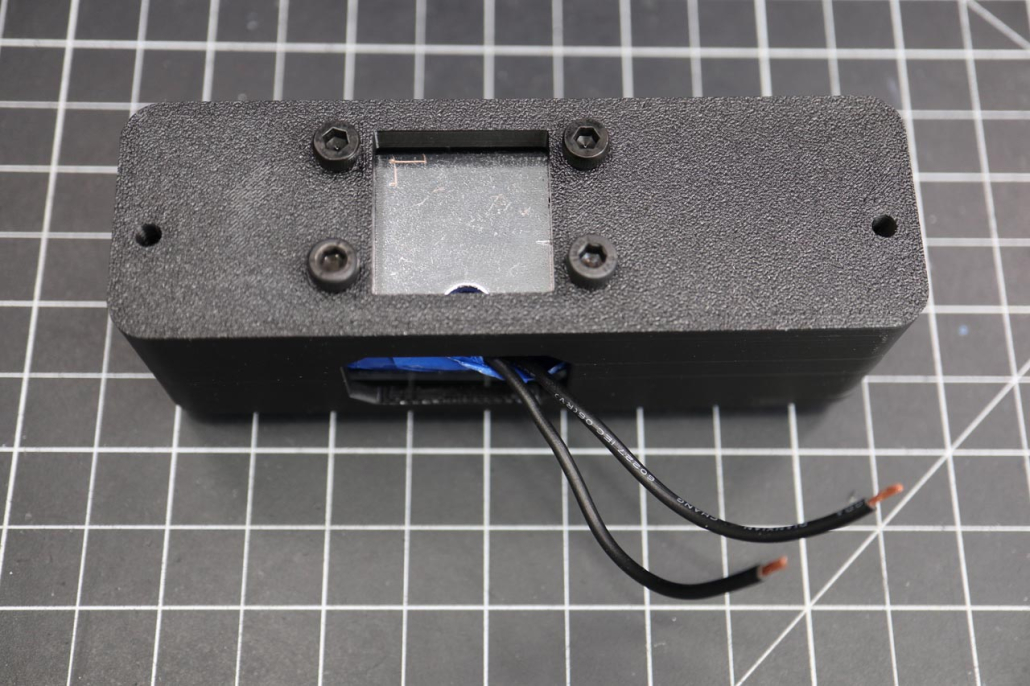
15 Prepare the Solenoid
PARTS
- JF-Z05 Solenoid
- 3D Printed Part:
- Button Head M4X6 4
STEPS
- Remove the stem from the slenoid
- Grasp the Solenoid by the thin shaft at the back with pliers
- Hold the Front with the spring still and unscrew the thin shaft until it comes apart
- Trim the solenoid wires to 70mm and strip the ends
- Insert the solenoid into the holder with the screw holes facing in so they line up with the holes on the 3D printed part
- Screw the solenoid to the holder with the 4 Button Head M4X6 screws
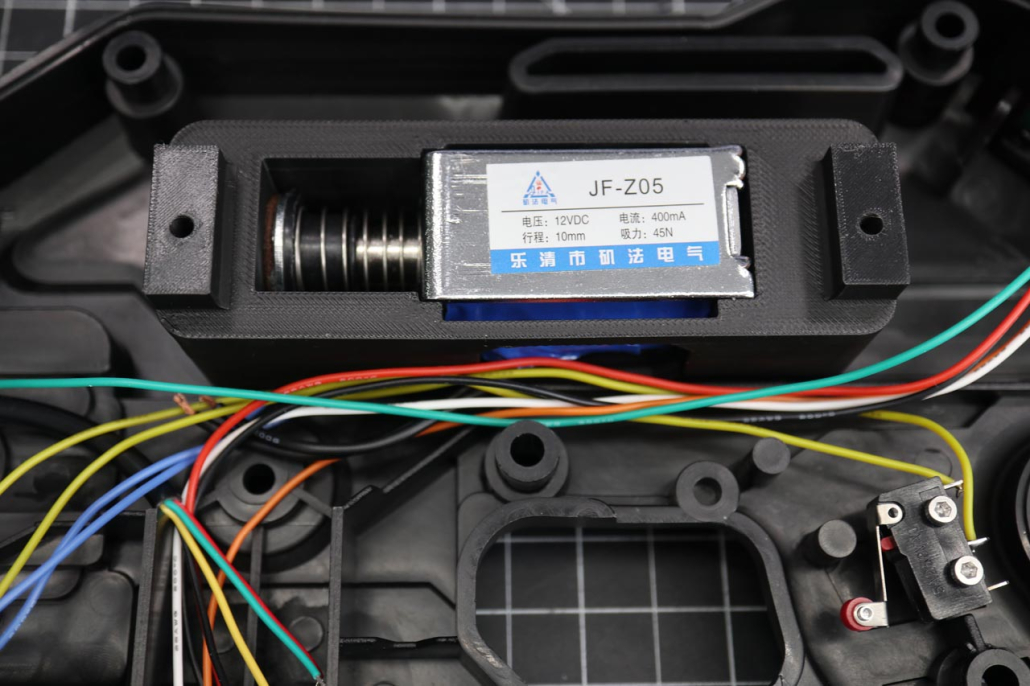
16 Install the Solenoid
PARTS
- Pan Head M4X16 X 2
STEPS
- Place the solenoid holder in the position shown
- The screw holes in the holder should line up with the screw holders in the frame
- Screw them together with 2 Pan Head M4X16 screws
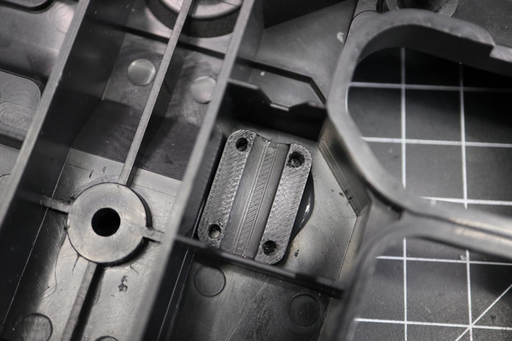
17 Glue in the Rumble Motor Mount
PARTS
- 3D printed part: Blamcon_AliensArcade_RumbleMountBot_V1
STEPS
- Hot glue or superglue the rumble holder in place as shown, be careful not to get glue into the screw holes
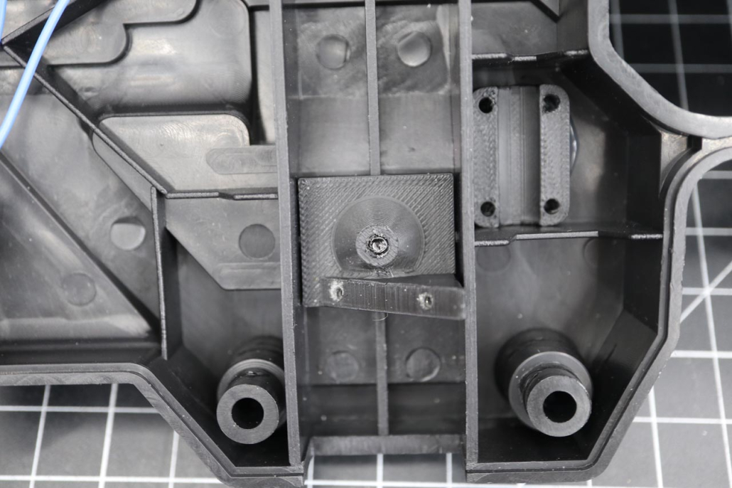
18 Screw in the Core Mount
PARTS
- 3D Printed Part: Blamcon_AliensArcade_CoreHolder_V1
- Pan Head M4X10
STEPS
- The core holder has a pattern on the back to line up with the screw hole, make sure it’s a lined and push it in to fit
- Screw the core holder into the body with a pan head M4X10 screw
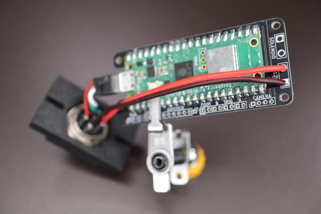
19 Solder the 12V and Connect USB
PARTS
- Premade GX16/USB connector
- Blamcon Core
STEPS
- Solder the 12V positive (1 on the GX16) to the 12V positive in (circle) on the core
- Solder the 12V negative (1 on the GX16) to the 12V positive in (circle) on the core
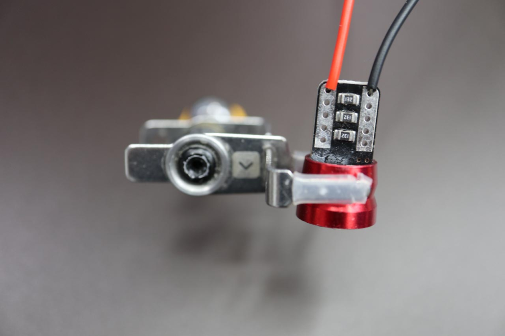
20 Solder the 12V Red LED (Optional)
PARTS
- 12V T10 W5W Red LED
- 100mm red wire
- 100mm black wire
STEPS
- Solder the red and black wire to the LED, polarity doesn’t matter
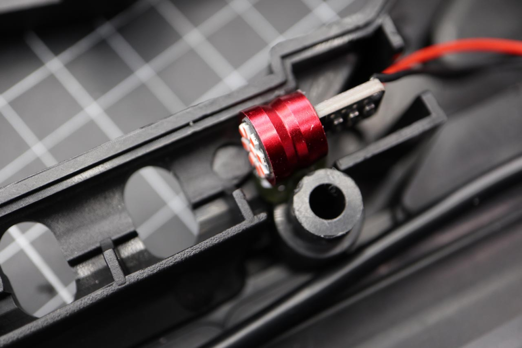
21 Glue in the 12V Red LED (Optional)
PARTS
- Presolderdd 12V Red LED
STEPS
- Glue the LED to the body in the position shown, add enough glue that it holds tight but not too much to impede the frame going together later
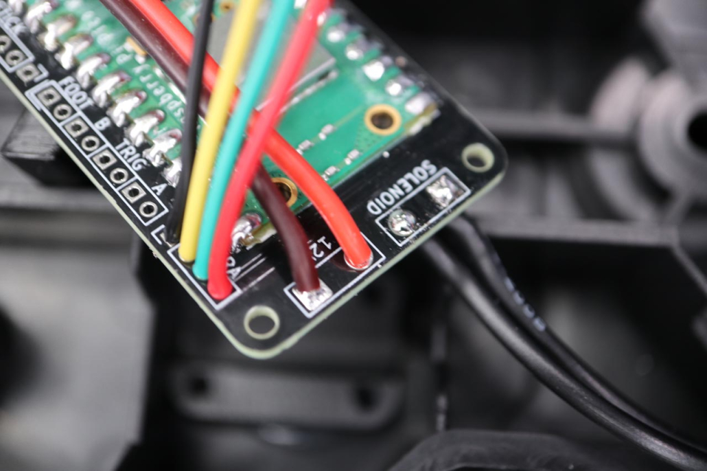
22A Solder the Solenoid and Camera (No 12V LED)
PARTS
- Prepared SEN0158 Camera
- Blamcon Core
STEPS
- Solder the Camera wires to the Camera port
- Black wire in the square hole
- Yellow wire next
- Green wire after
- Red wire on the end
- Solder the Solenoid wires to the Solenoid port on the core, polarity doesn’t matter.
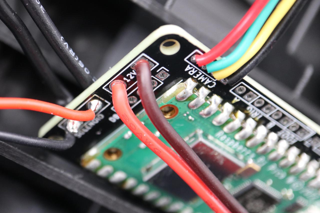
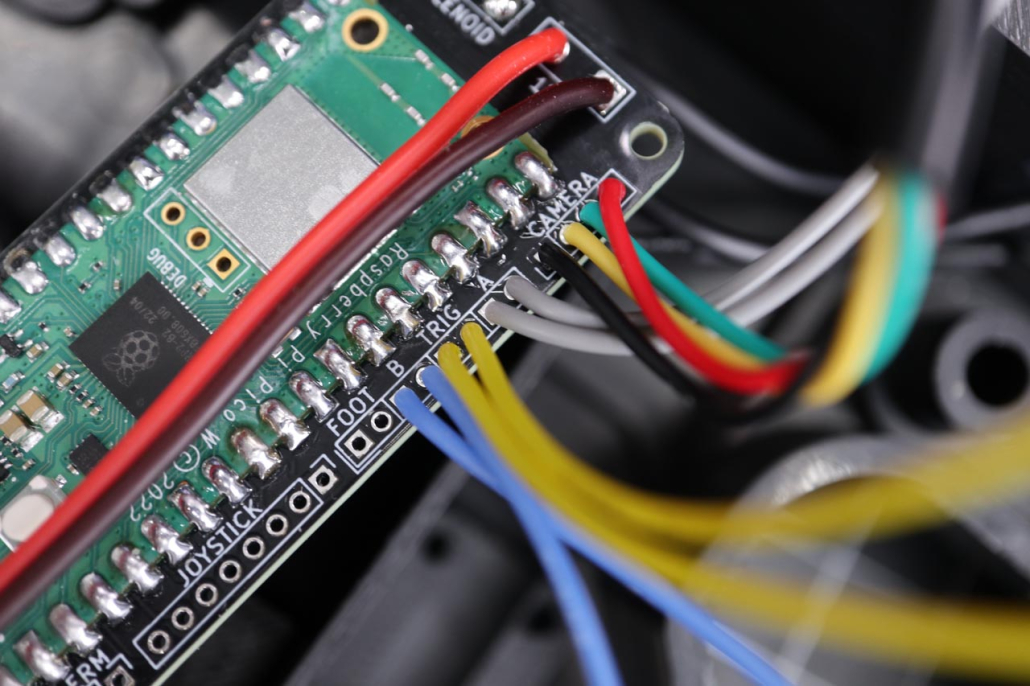
22B Solder the Solenoid and Camera (No 12V LED)
PARTS
- Prepared SEN0158 Camera
- Blamcon Core
STEPS
- Solder the Camera wires to the Camera port
- Black wire in the square hole
- Yellow wire next
- Green wire after
- Red wire on the end
- Solder the Solenoid wires and 12V LED to the Solenoid port on the core, polarity doesn’t matter. I find it’s easier to solder the solenoid on the bottom and LED on the top
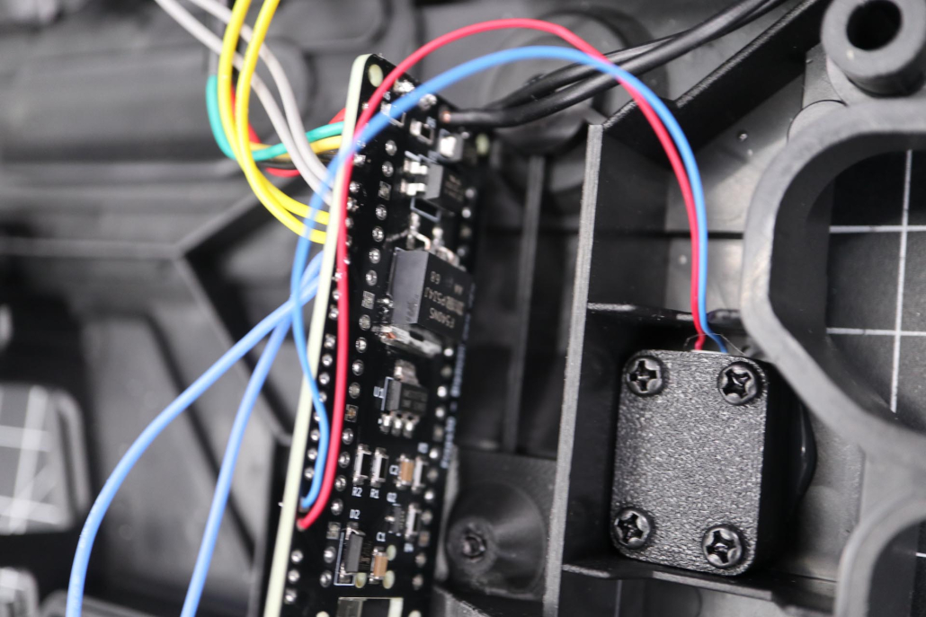
23 Solder the A/B/Trigger
PARTS
- Presoldered trigger
- Presoldered A button
- Presoldered B button
STEPS
- Solder the trigger to the TRIG port
- Solder the A button to the A port
- Solder the B button to the B port
Note: Polarity doesn’t matter for buttons so solder either wire to either hole
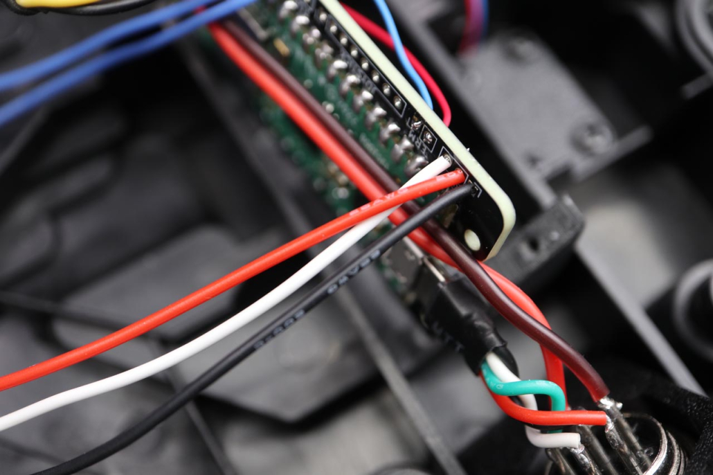
24 Solder the Rumble
PARTS
- 3D Printed Part: Blamcon_AliensArcade_RumbleMountTop_V1
- Pan Head M3X10 X 4
- Blamcon Core
STEPS
- Trim the rumble wires (or extend them if it’s short) to 115mm
- Screw the rumble motor into the mount
- Solder the rumble motor to the ERM port on the core
- Red to circle
- Blue to squre
25A Solder the LED
PARTS
- Presoldered Neopixel LED
- Blamcon Core
STEPS
- Solder to the LED port on the core
- Ground to Square (black)
- 5V in the middle pin (red)
- Din to the last pin (white)
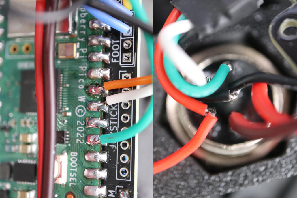
25B Solder the Counter
PARTS
- Presoldered counter
- Blamcon Core
STEPS
- Note: The counter isn’t something natively supported by the 1.6 core so you’ll have to solder onto the pins, this can be a delicate process. If you’re not comfortable doing this just use the LED version which is very simple.
- Solder the following
- GPIO5 (Pin7) to Counter SDI (Green)
- GPIO6 (Pin9) to Counter SCL (White)
- GPIO7 (Pin10) to Counter LOAD (Orange)
- GX16 pin 3 or VBUS to Counter VCC 5V (red)
- GX16 pin 6 or any ground pin on the pico to Counter GND (black)
Note: The to the counter is 5V! If you solder it to GX16 pin 1, 12V, you will cook it the second you add power.
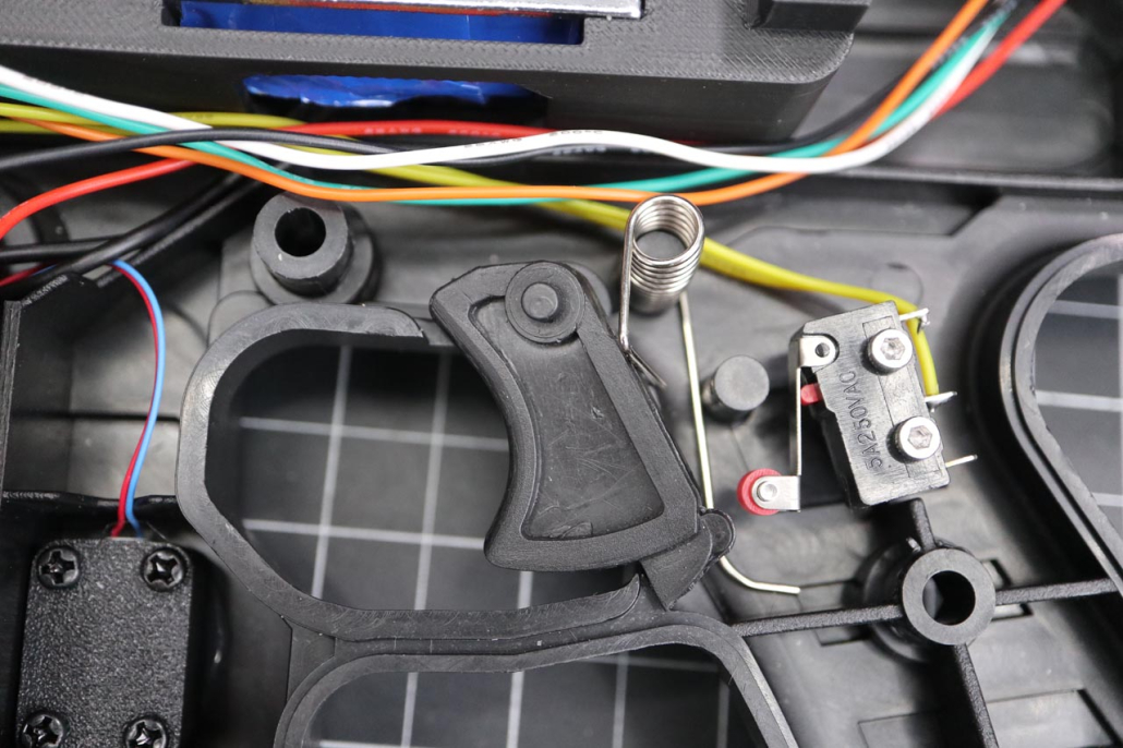
26 Install the Trigger
PARTS
- Trigger
- Trigger spring
STEPS
- Insert the trigger and trigger spring as shown
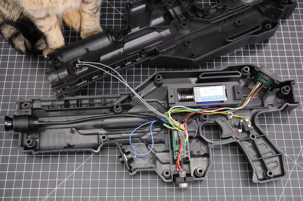
27 Ready to Put Together
STEPS
- Before putting it together observe the image and route the wires as shown, it shouldn’t pinch in the frame anywhere. If needed you can use a drop of hot glue or tape in places to keep the wires out of the way.
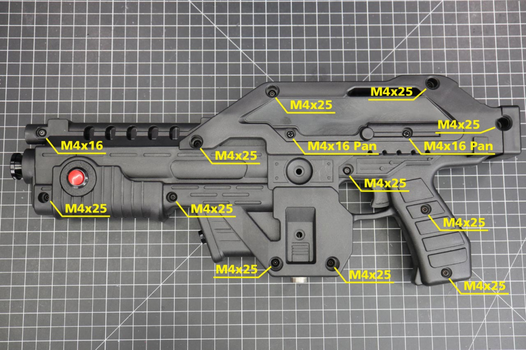
28 Screw it Together
PARTS
- Button Head M4x16
- Button Head M4x25 X 11
- Pan Head M4x16 X 2
- M4 Nut X 12
STEPS
- Screw the other half of the solenoid mount on with the 2 M4x16 cap head screws
- Screw the body together as shown, use a button head M4x16 screw for the front of the barrel and the rest are button head M4x25 screws, use a nut to back each one.

28 All Done!
- Screw the other half of the solenoid mount on with the 2 M4x16 cap head screws
- Screw the body together as shown, use a button head M4x16 screw for the front of the barrel and the rest are button head M4x25 screws