
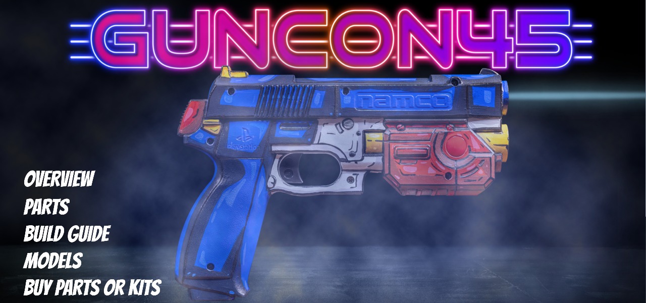



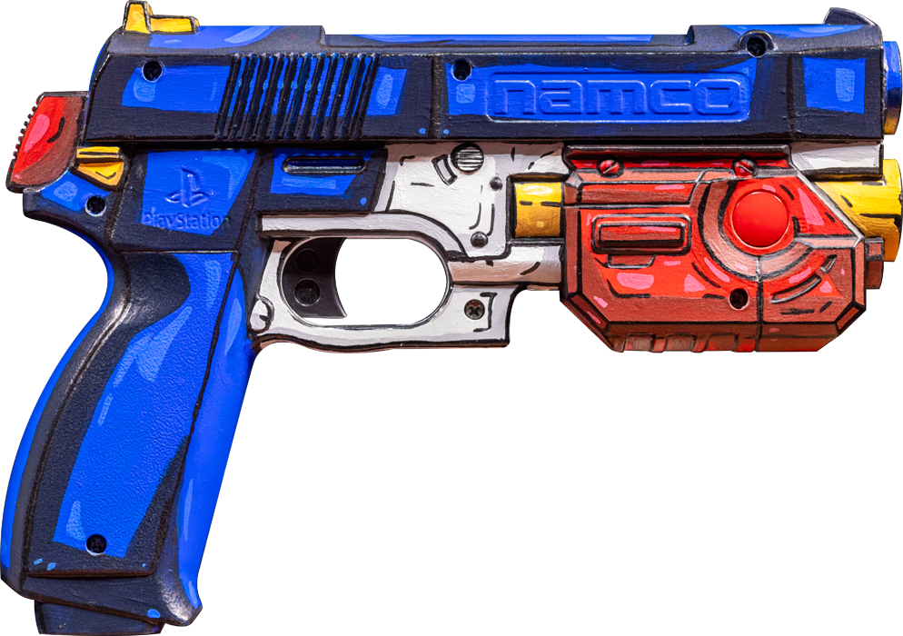


The Namco G-Con 45, or just the GunCon is probably the most iconic light gun in existence. With millions made and almost a household item this is probably the easiest light gun to obtain for conversion, and one well worth the time. It was often bundled with Point Blank or Time Crisis, and is often referred to as ‘The Time Crisis Gun’. The Blamcon conversion preserves the original side buttons and adds a microswitch to the trigger to improve feel and responsiveness. The conversion also features solenoid recoil, rumble, and RGB LED for feedback.
Wire Lengths
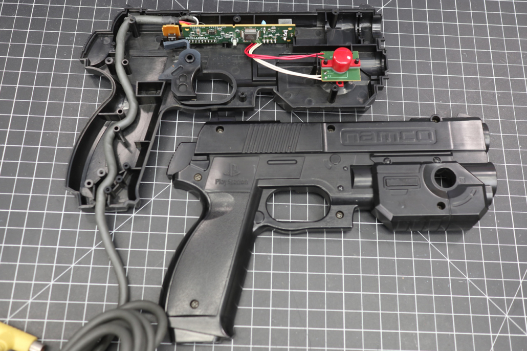
1 Open it Up
- Remove the 7 screws on the right side that hold it together
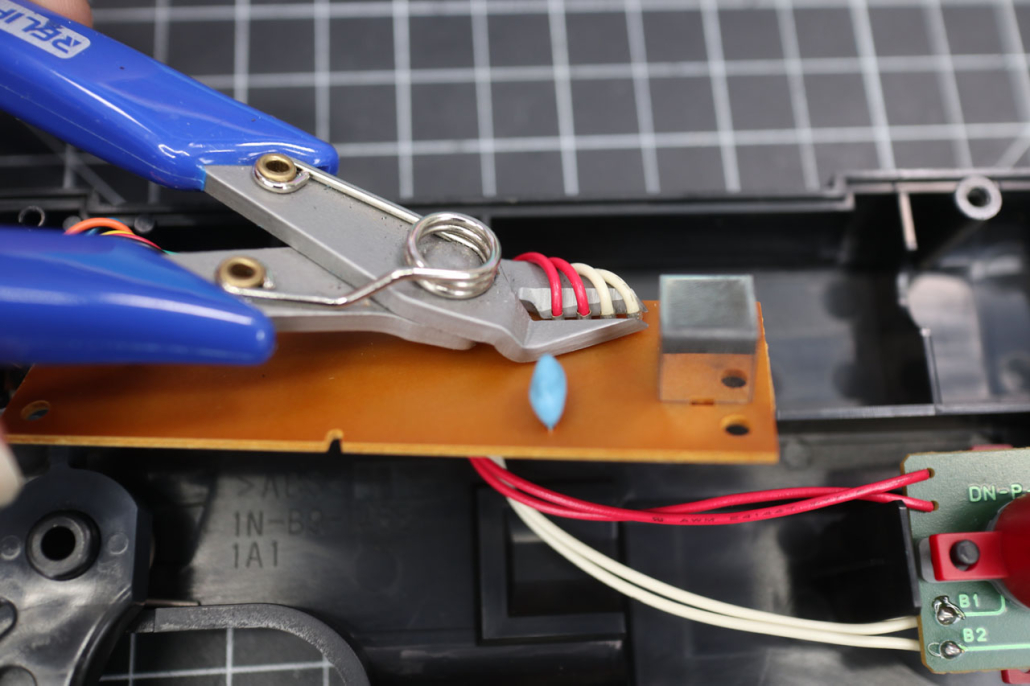
2 Cut the Buttons off the Board
- Use side cutters to cut the 4 wires that connect to the forward A/B buttons.
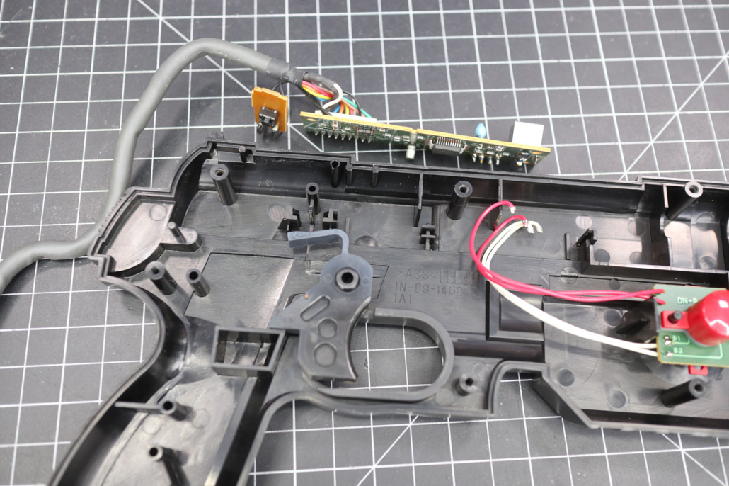
3 Remove the Electronics
- Remove the electronics as shown, it all should come out as one piece
- Leave the forward A/B buttons in place.
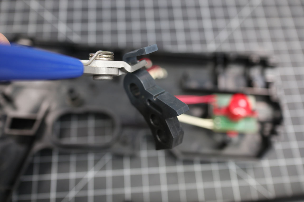
4 Cut the Trigger Tab
- Using a Dremel or side cutters, remove the switch actuator as shown
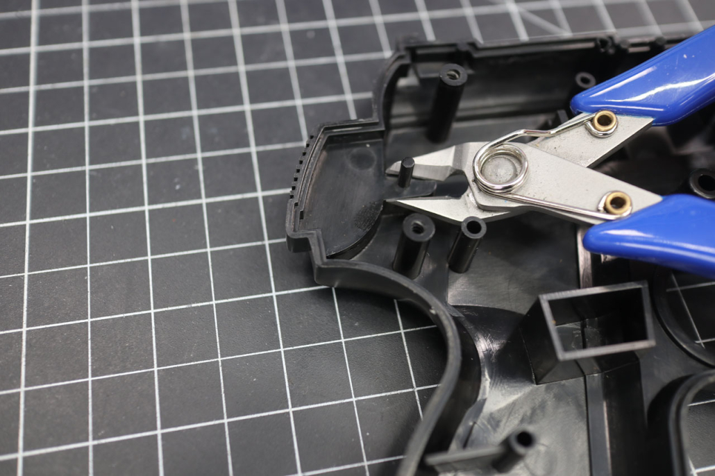
5 Remove the Pin
- Using side cutters or a knife remove this small post from the left side of the frame
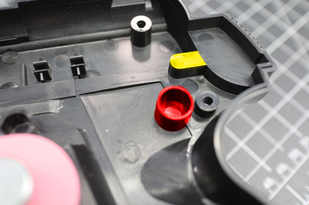
6 Modify the Right Frame
- Remove the post (shown in red) by trimming it down with a Dremel or cutting it down and pulling it apart with side cutters, it should be close to flush when you’re done, it doesn’t have to be perfect
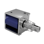
- Using a Dremel, file, or chisel. Trim the part marked in yellow down 2mm. This is to allow movement of the solenoid.
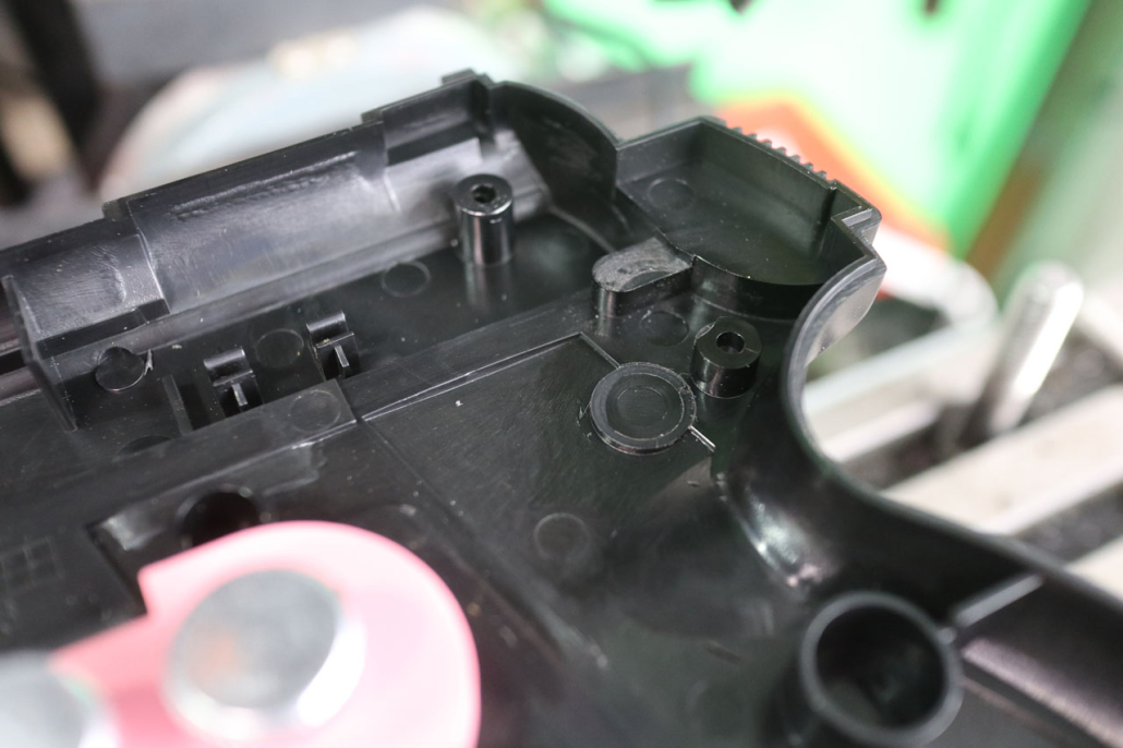
7 Right Frame Modification (After)
- The post is removed
- The raised part at the rear has been cut down by 2mm
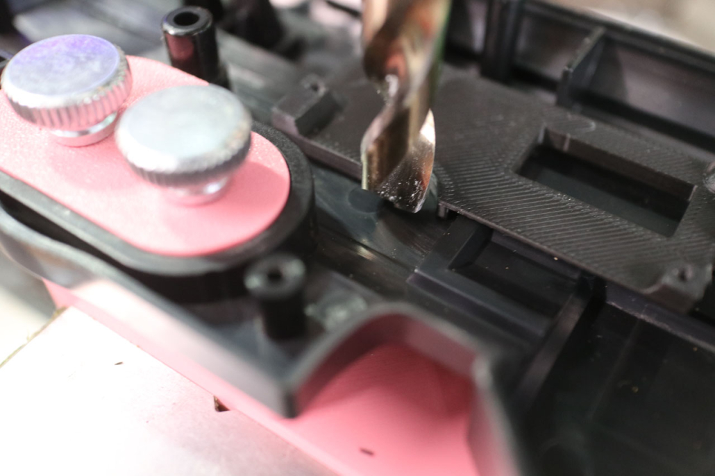
8 Make a hole for the LED
- Place the 3D printed PCB holder in the location shown, the small hole in the holder should line up with the tab in the frame and it should fit snug.
- Using the the LED cutout on the PCB holder, drill a 10mm hole in the frame, be very careful when doing this. The LED cutout is 12mm and the hole is 10, this is to leave a lip for the LED diffuser to sit on.
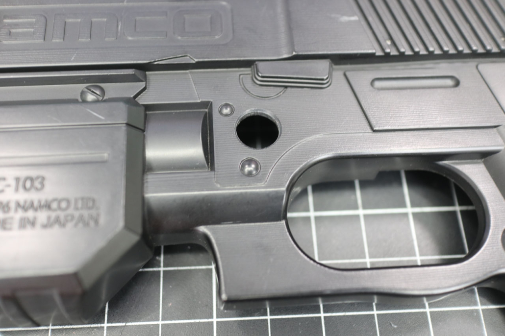
9 LED Hole Done
- When flipped over the LED hole cut in step 9 should look like this, optionally add a slight chamfer for looks
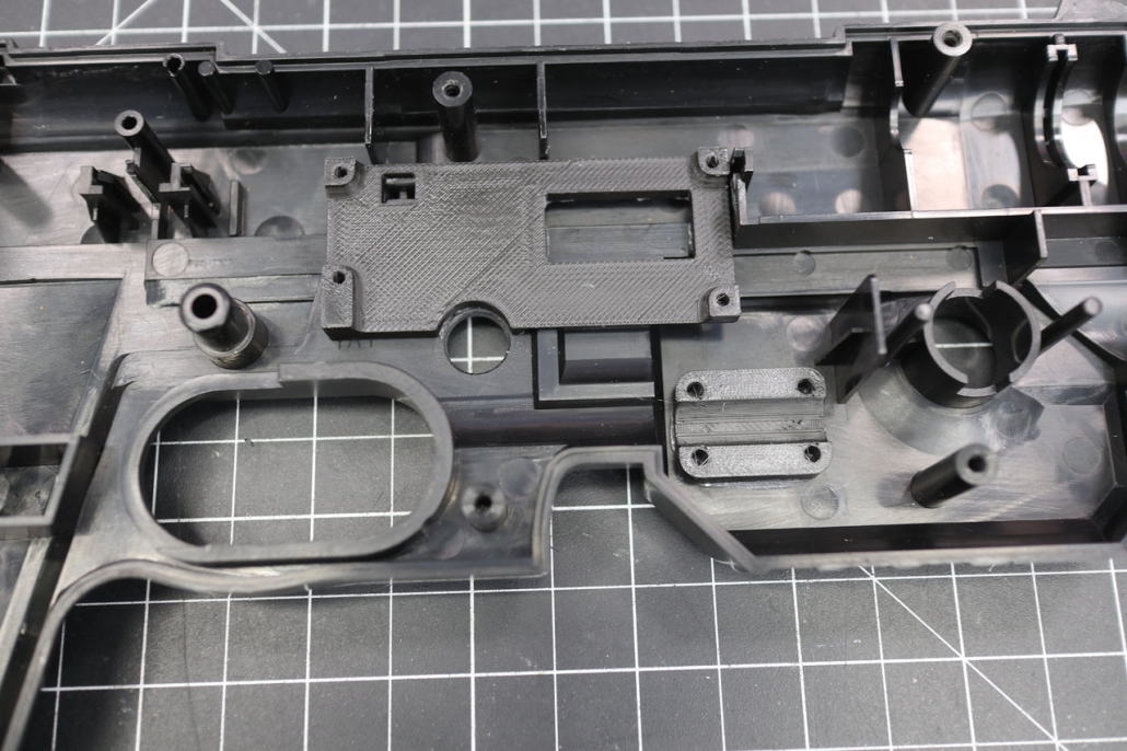
10 Glue the Holders In
- Glue the PCB Holder as shown. Use superglue for speed or epoxy if you want to be sure as you can move it around for a bit after
- Glue the rumble holder half with the SMALLER holes in as shown
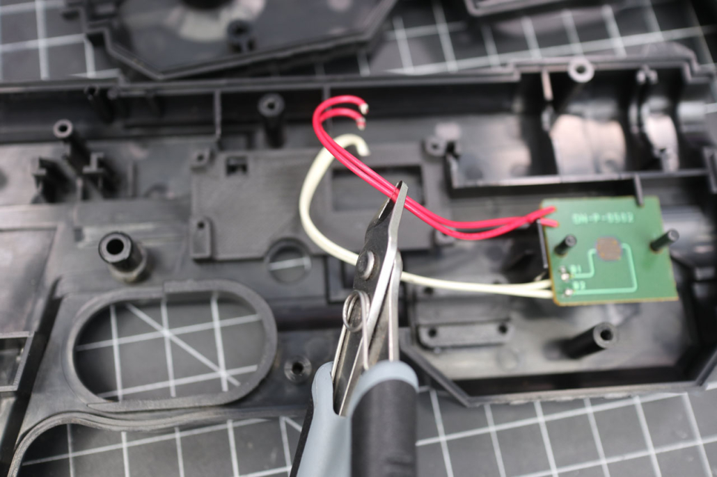
11 Trim the A Button Wires
- Using side cutters trim the A button to ___mm
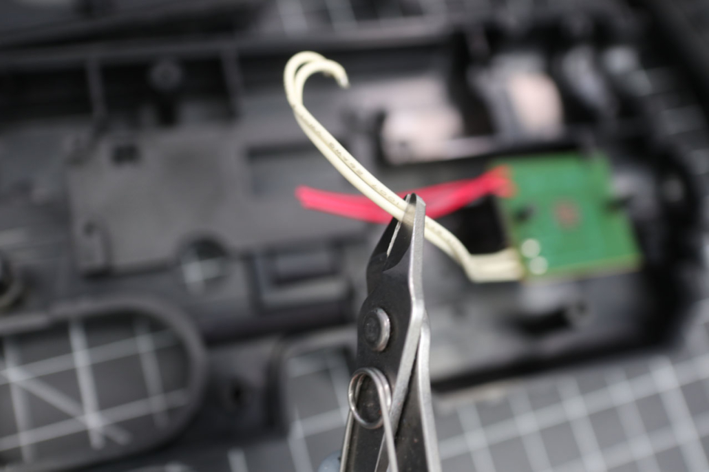
12 Trim the B Button Wires
- Using side cutters trim the B button to ___mm
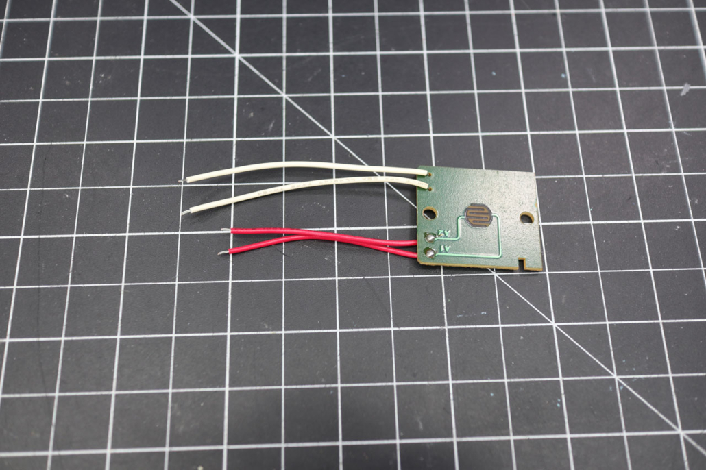
13 Prepared A/B Buttons
- Strip the ends of the A/B button wires
- The prepared A/B Button module should look like the picture
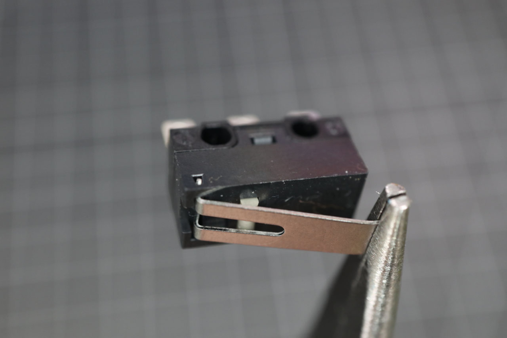
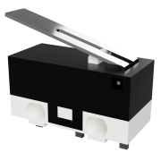
14 Bend the Microswitch
- Using a pair of pliers grip the very end of the microswitch.
- Push on the metal leaf. NOT the switch, right where it’s held by the piers to put a small bend in it.
- This gives the trigger a bit of a smoother action, it is a VERY small bend, a large bend will prevent the trigger from actuating the switch
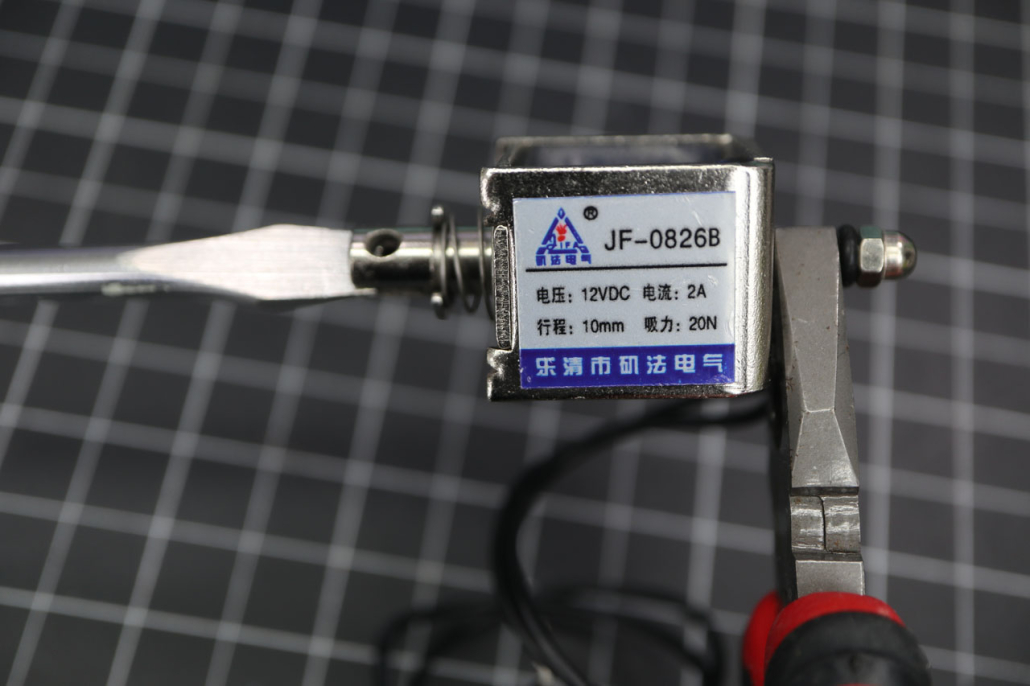
15 Prepare the Solenoid
- Grip the small shaft of the solenoid with piers as shown
- Using a flat bladed screwdriver unscrew the small shaft and discard it
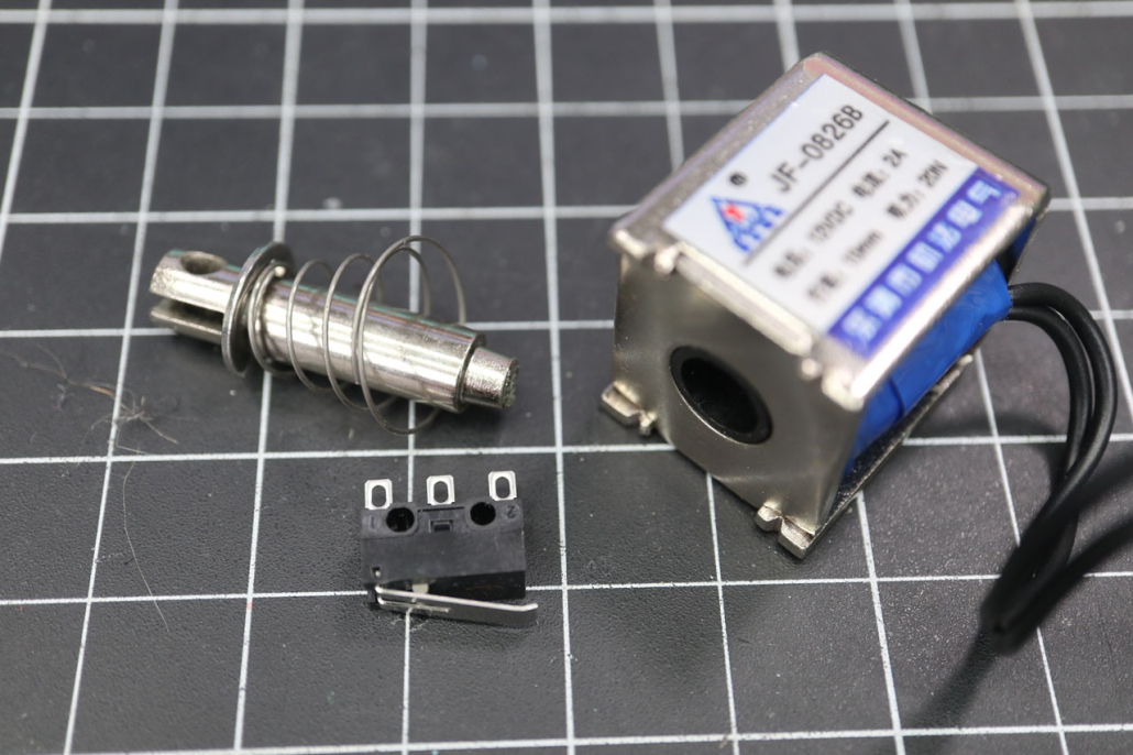
16 Prepared Solenoid and Trigger
- Small Solenoid shaft is removed, larger actuator and spring is kept
- Trigger has a small bend to help smooth movement
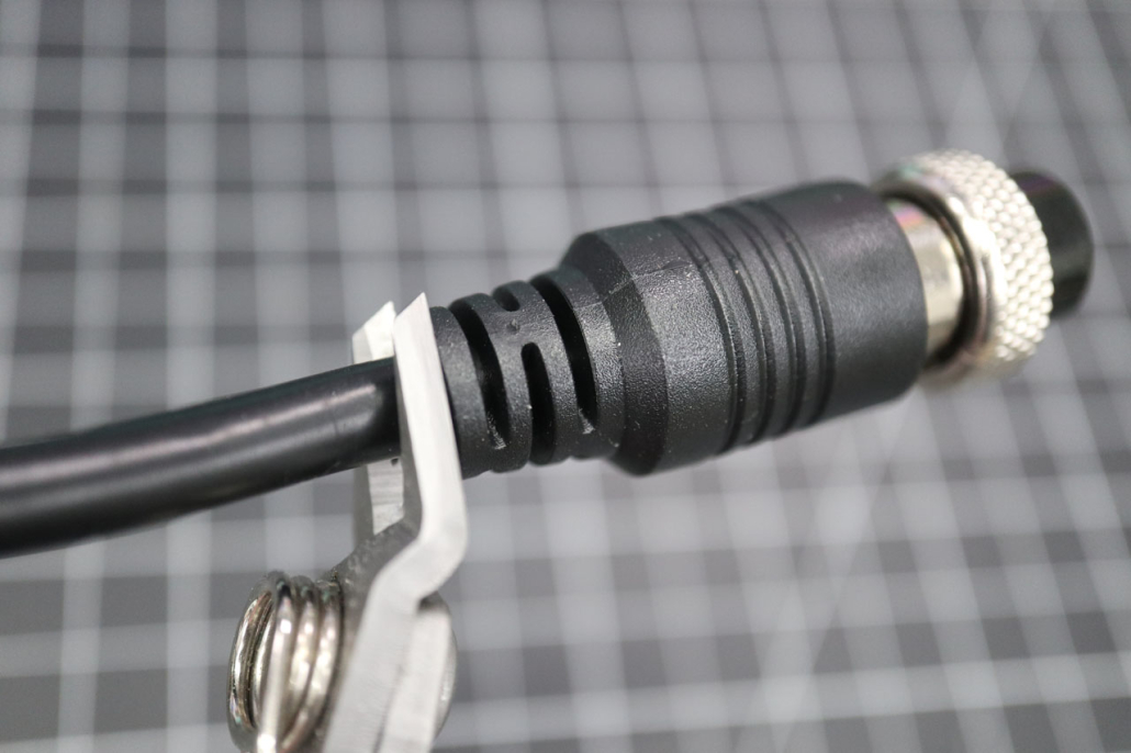
17 Prepare the Cable
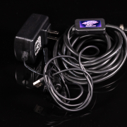
- This can vary wildly depending on what cable you use. We are using an 8 pin GX16 here and cutting the connector off but you can use a 6 pin just as easily, the requirement is 4 wires for USB and 2 for solenoid.
- If you want you can use the original included GunCon cable and just solder a USB/2.1barrel female on it, the choice is yours!
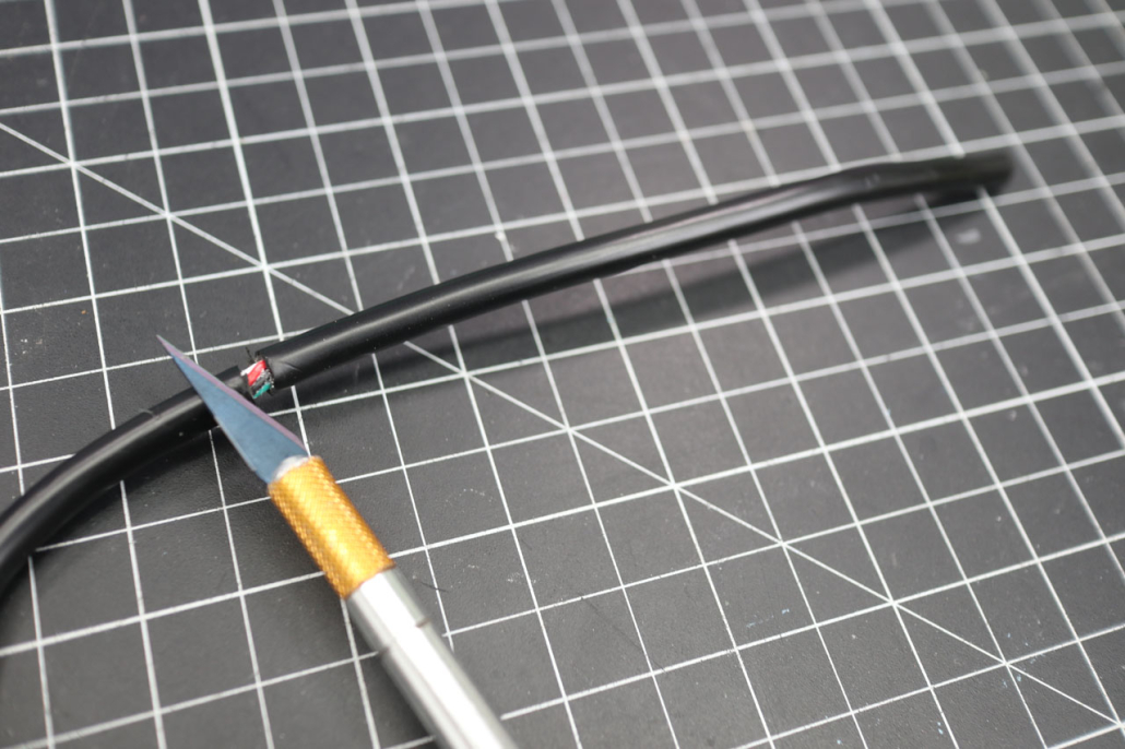
18 Strip the cable
- Make a small cut 14.5 CM down the wire around the insulation, DO NOT CUT DEEP! A shallow cut will allow you to rotate the wire and the rest should break
- Pull off the insulation exposing the wires inside.
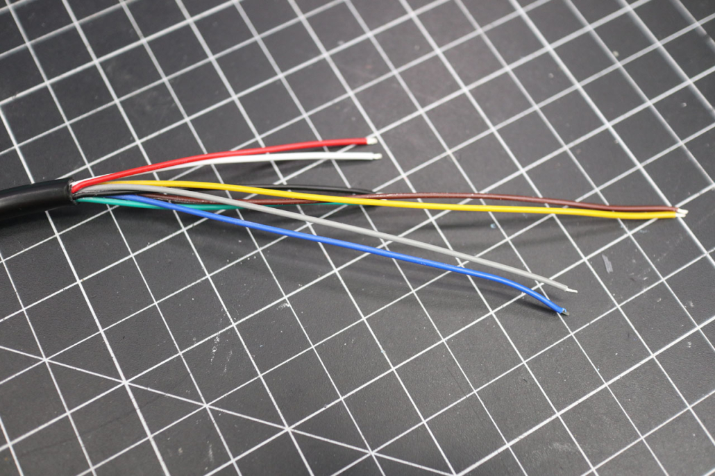
19 Prepare the Wires
- Do NOT trim the Brown or Yellow wires
- Cut the foot petal (if present) Gray and Blue wires 2CM shorter than the yellow wire
- Cut the USB wires Red/White/Green/Black wires 7.5CM shorter than the yellow wire
- Strip all 6/8 wires
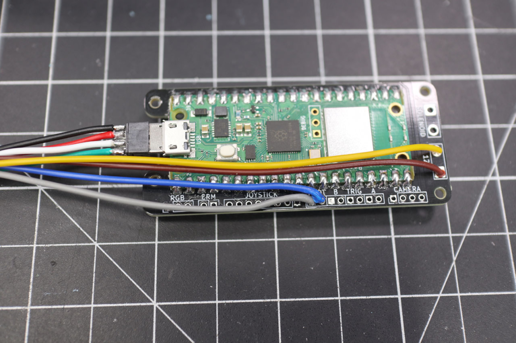
20 Solder the Cable Wires
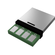
- Solder the USB connector on, be careful of your USB connector pinout
- Solder the 12V input, negative to the square pad, positive to the circle (important!)
- If you have an 8 pin wire with a foot petal connector you can connect to the foot petal connector, polarity is not important
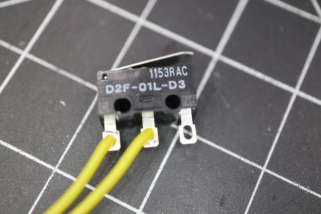
21 Solder the Trigger Microswitch
- Solder the Yellow 11cm wires to the two poles
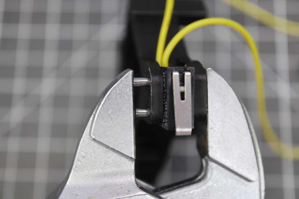
22 Insert the Trigger Pins
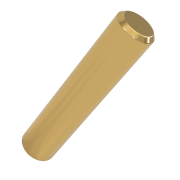
- Press fit the 2mm bars into the 3D print to hold the trigger.
- You may have to enlarge the hole a bit, if it gets too big a bit of epoxy will fix it up
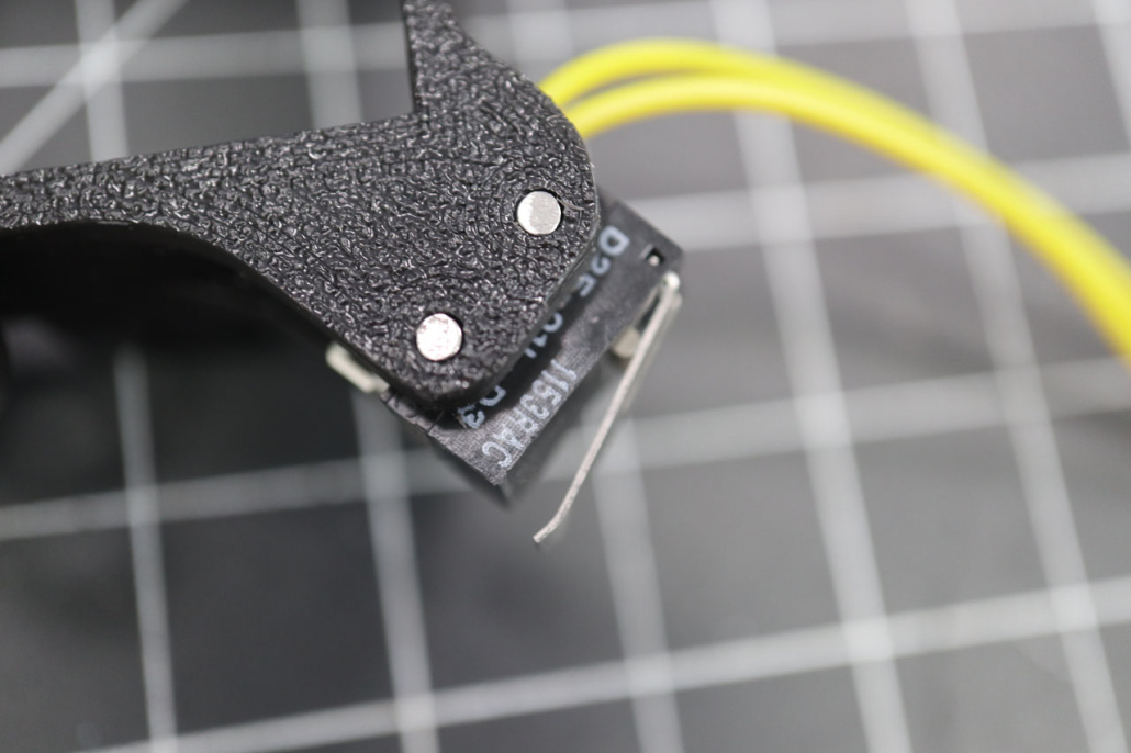
23 Trigger Ready to Go
- Press fit the 2mm bars into the 3D print to hold the trigger.
- You may have to enlarge the hole a bit, if it gets too big a bit of epoxy will fix it up
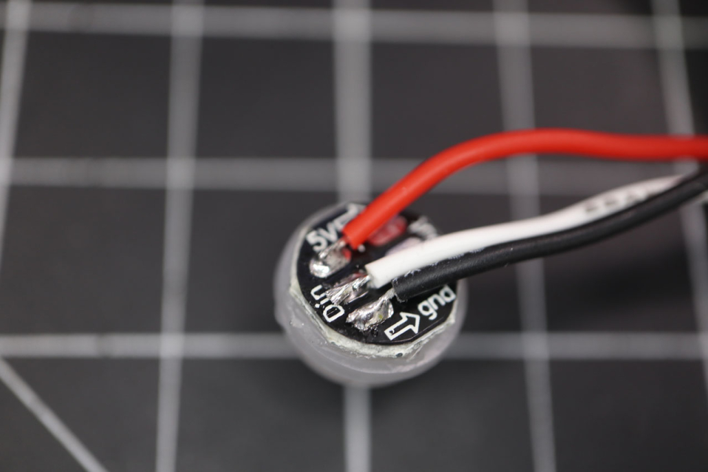
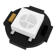
24 Solder the LED wires
- Solder the LED wires as shown
- Red to Positive
- White to Signal
- Black to Ground
- Note that the diffuser is held onto the LED by hot glue, this is predone in kits but if you’re building yourself there’s a diffuser 3D model if you need it.
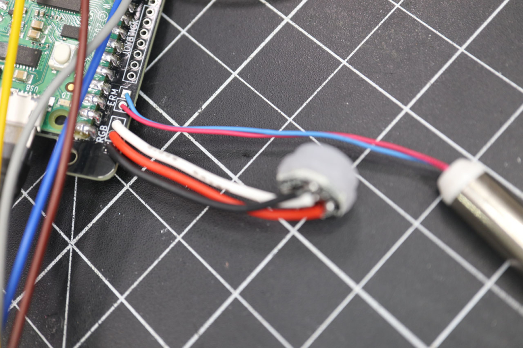
25 Solder the LED and Ruble onto the Core
- Solder the LED to the core to the LED connector
- Black wire to the square hole
- Red wire next
- White wire on the end
- Solder the Rumble motor to the core on the ERM connector
- Blue wire to the square hole
- Red wire to the other hole
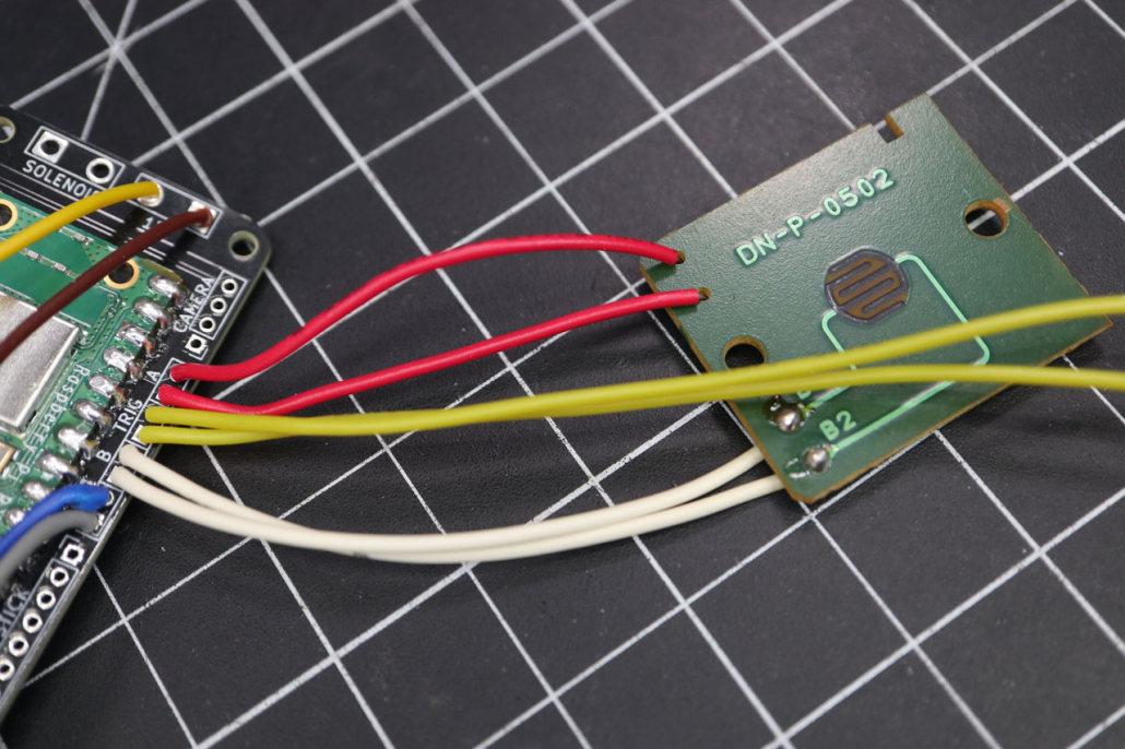
26 Solder the Buttons and Trigger onto the Core
- Solder the Yellow trigger wires onto the core
- Solder the Red A wires onto the core
- Solder the White B wires onto the core
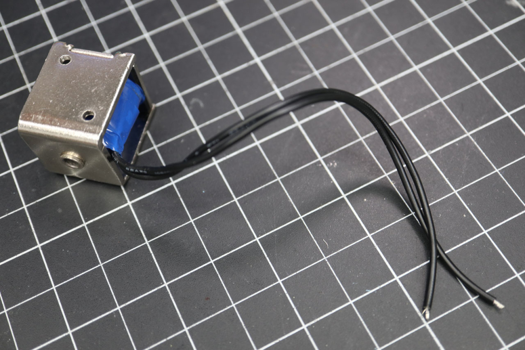
27 Prepare the Solenoid
- Cut the solenoid wires to 13.5CM from where they come out of the solenoid
- Strip the ends
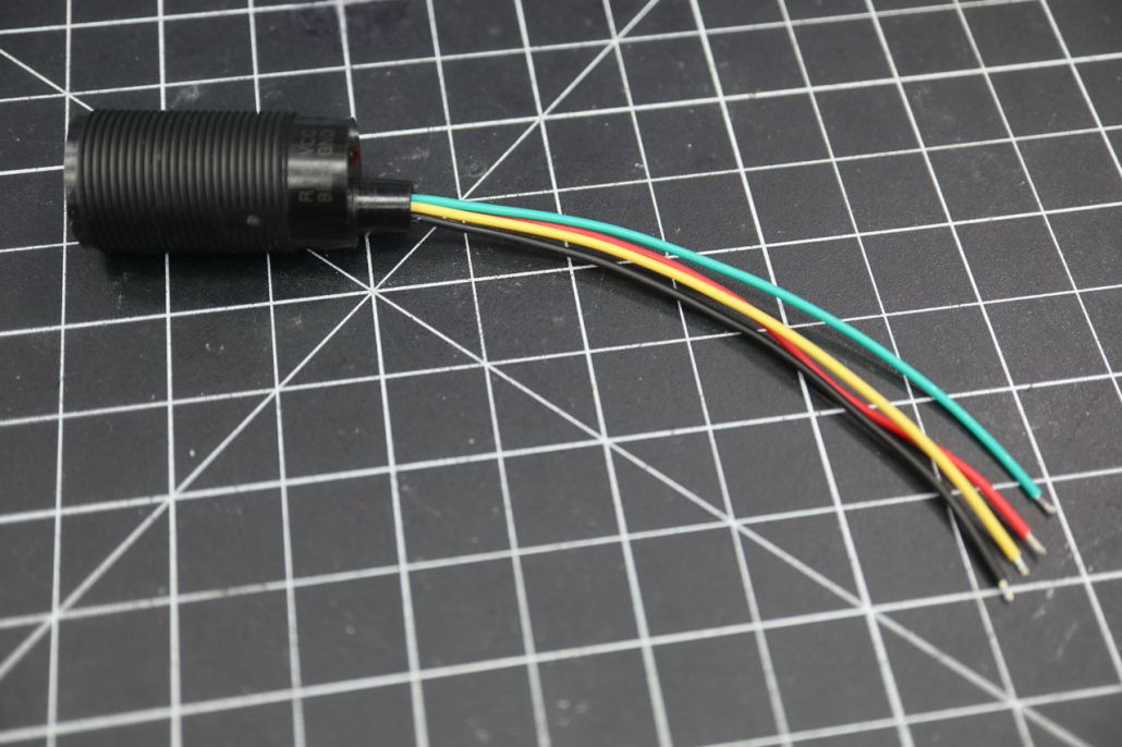
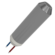
28 Prepare the Camera
- Cut the camera wire 7.5CM from the base
- Pull off the insulation, slowly, to expose the wires
- Strip the ends of the wire
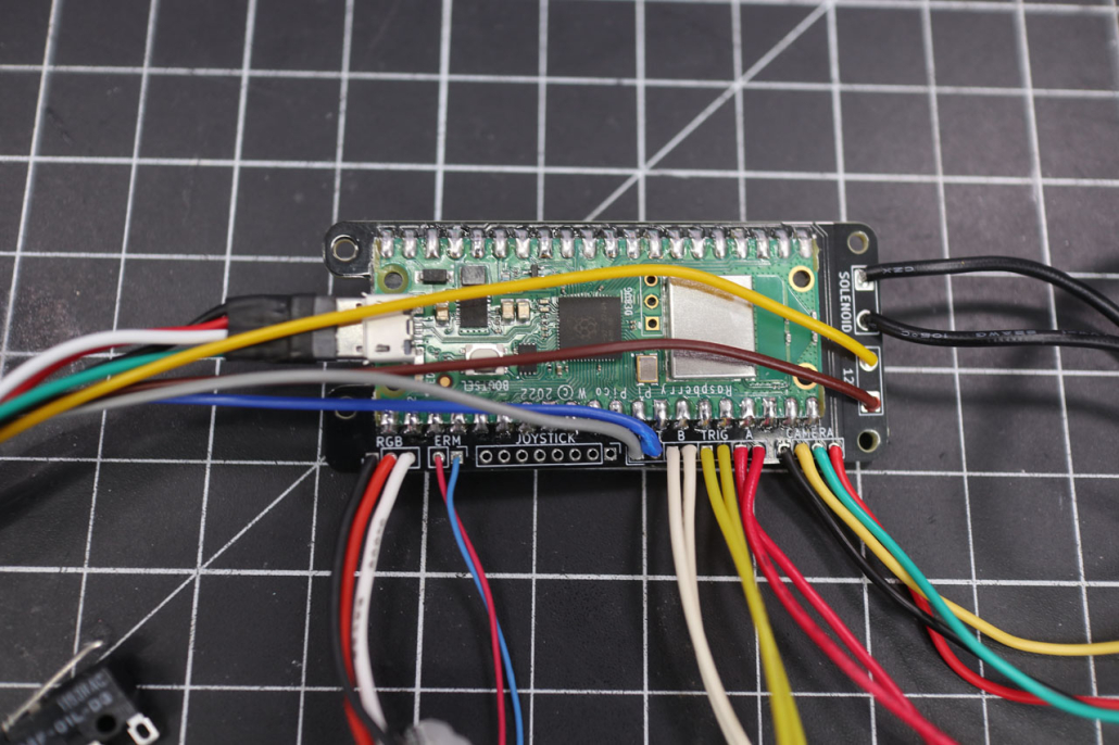
29 Solder the Camera and Solenoid to the Core
- Solder the Solenoid wires to the Solenoid port
- Solder the Camera wires to the Camera port
- Black wire in the square hole
- Yellow wire next
- Green wire after
- Red wire on the end
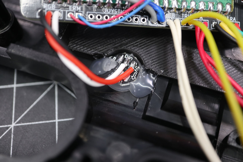
30 Glue in the LED
- Solder the Solenoid wires to the Solenoid port
- Solder the Camera wires to the Camera port
- Black wire in the square hole
- Yellow wire next
- Green wire after
- Red wire on the end
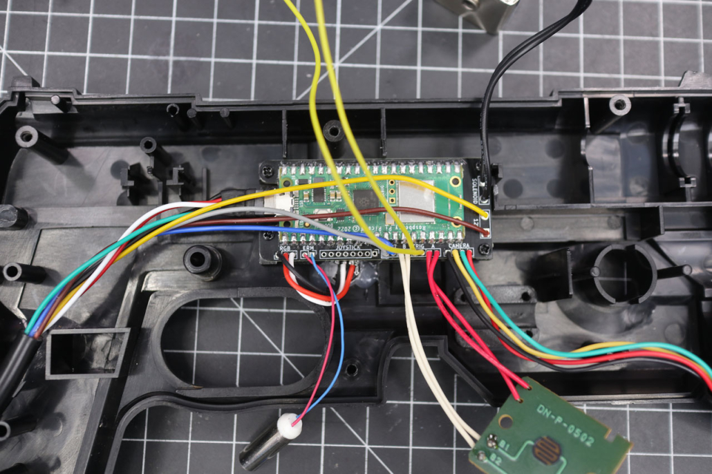
31 Screw in the Core
- Move the parts as shown, making sure wires don’t cross
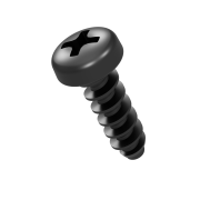
- Screw the core in using M2x5mm screws
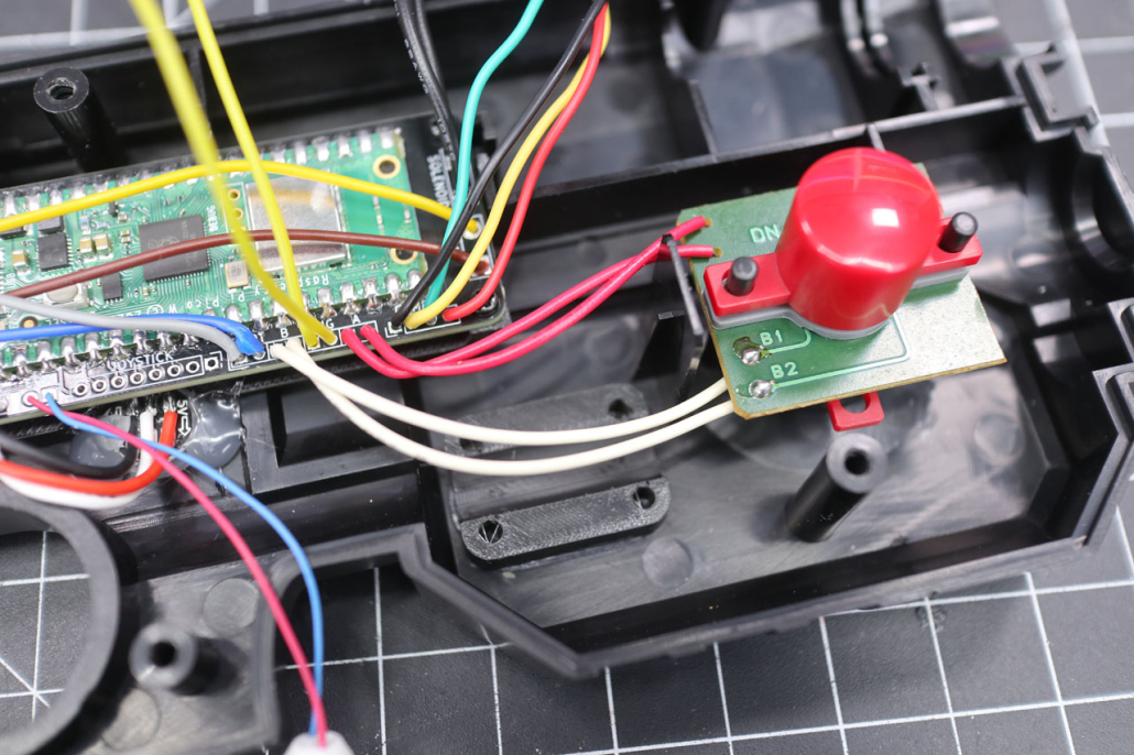
32 Reinstall the A/B Buttons
- Place one of the buttons into the button hole
- Insert the round rubber pad into the button with the part that sticks out facing into the button
- Place the A/B button PCB in making sure the White wires are on the bottom
- Place the rubber pad with the two tabs over the posts as shown
- Slide the second button down the posts on top of the rubber pad
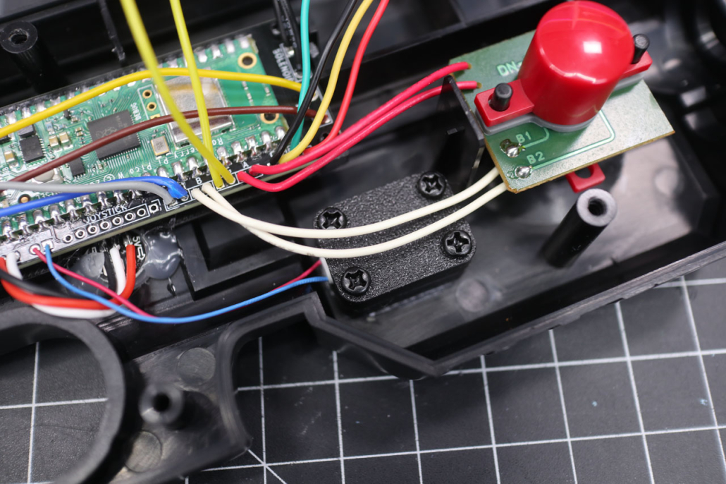
33 Install the Rumble
- Insert the rumble into the holder
- Screw the 3D printed rumble holder on top using M3X10 screws
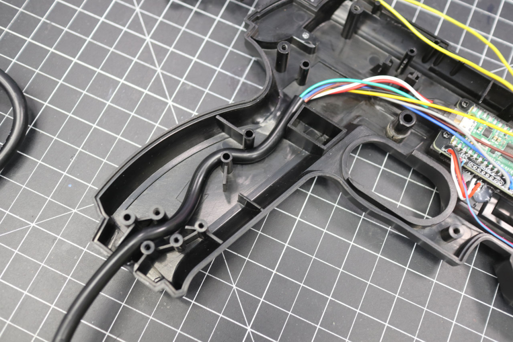
34 Route the Cable
- Route the connection cable as shown, make sure the part of the wire without insulation is between the past curve but not high enough it will interfere with the trigger/rumble holder
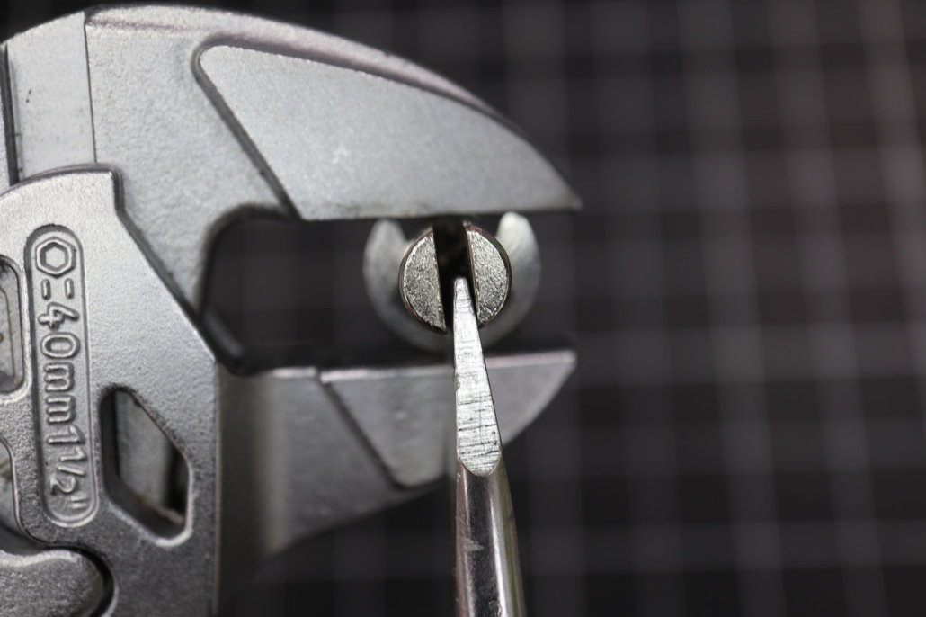
35 Align the Solenoid Actuator
- Using pliers and and a screwdriver rotate the c-ring on the solenoid actuator so the gap is aligned as shown
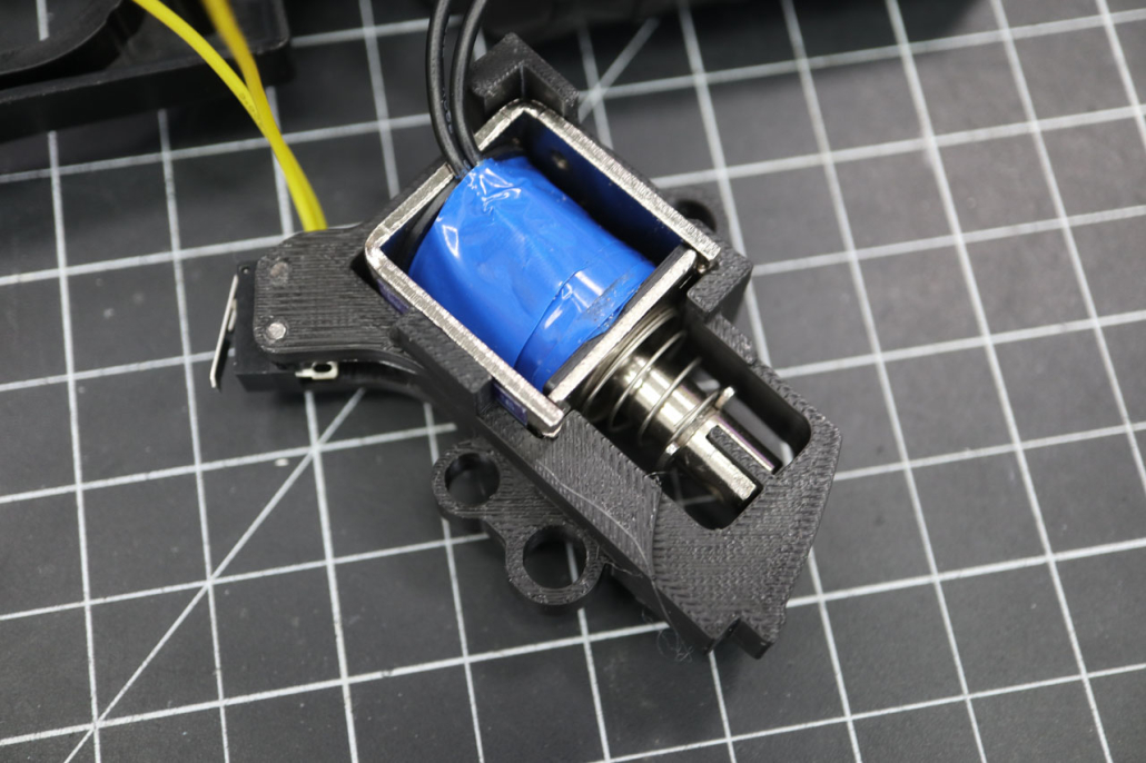
36 Install the Solenoid into the Holder
- Insert the solenoid actuator and spring into the solenoid
- Slide the solenoid into the frame as shown while holding the actuator down, slide it in from this side to make sure the wires are aligned as shown
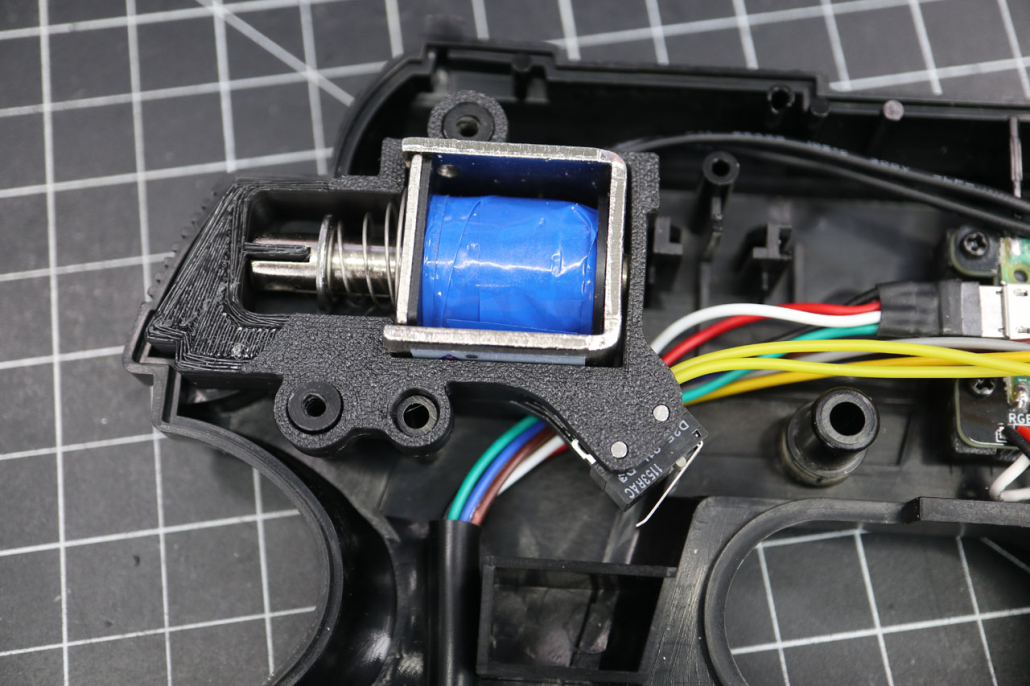
37 Install the Solenoid and Microswitch
- The solenoid wires should be coming out of the TOP as shown to not interfere with the trigger, you can do it out the side if you’re careful but no good reason to
- Slide the solenoid holder onto the posts as shown, make sure no wires are under the holder where it contacts the frame!
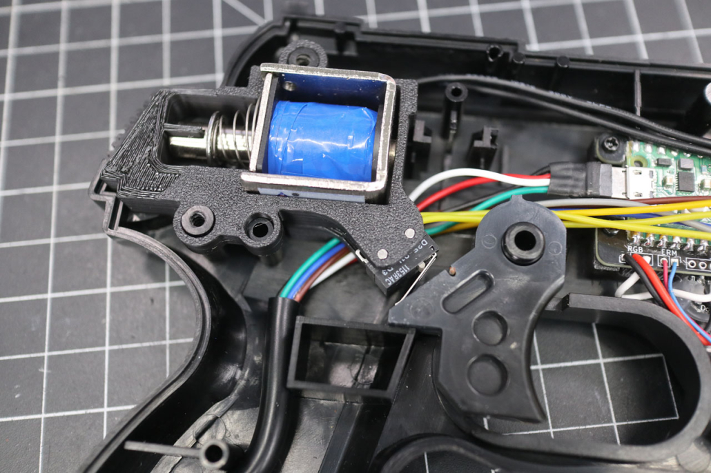
38 Install the Trigger
- Solder the Solenoid wires to the Solenoid port
- Solder the Camera wires to the Camera port
- Black wire in the square hole
- Yellow wire next
- Green wire after
- Red wire on the end
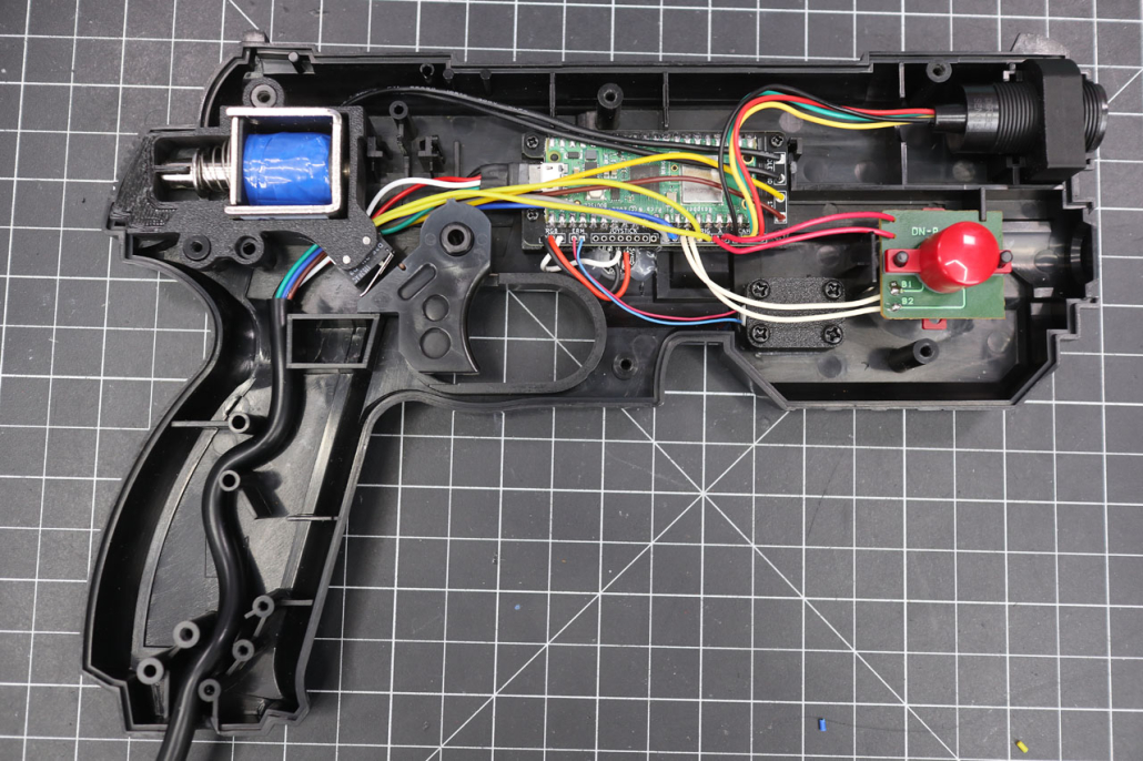
39 Install the Camera
- If you’re going to be using the wide angle lens adapter skip this step
- Thread the camera into the camera holder, it should be snug when going in but not too tight, if it’s tight you can sand the camera threads or print again with a lower extrusion multiplier. If it’s loose you can apply a bit of paint to the adapter (let it dry before tightening) or print with a higher extrusion multiplier. It needs to rotate for alignment but be tight enough it’ll stay where you want
- Thread the camera far enough through you can rotate it with your finger, this will allow you to adjust it later
- After alignment you CAN glue it in place, a drop of hot glue on the base is recommended if you do because it’s removable
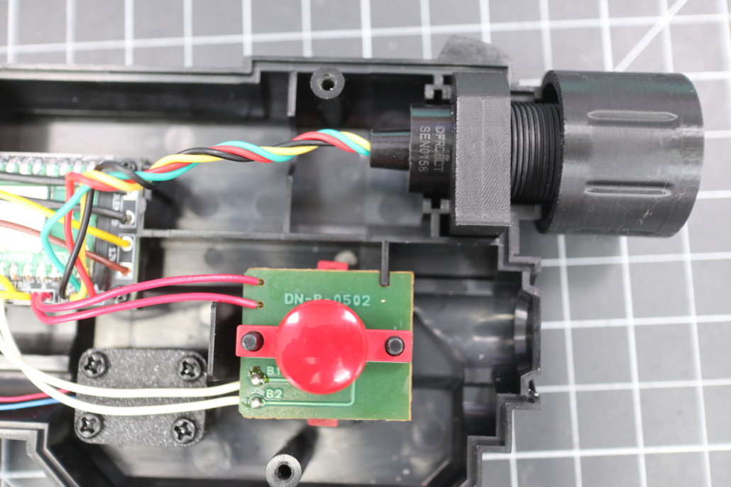
40 Install the Camera with Wide Angle Lens
- Screw the camera holder on until it’s all the way down the camera, there shouldn’t be any threading showing
- Screw on the wide angle lens into the lens adapter, make sure it’s flush with the adapter
- Screw the camera onto the wide angle lens adapter until it’s flush with the lens, there shouldn’t be any space
- Be careful with the threading above, the lens is .75mm and the camera is 1mm, it can cross-thread if you’re not careful
- Spin the camera holder until the lip of the lens adapter is just barely clear of the barrel, then take it out and twist the camera wires 4 times counter-clockwise as shown, when you put it together and screw the adapter down this will untwist the wires.
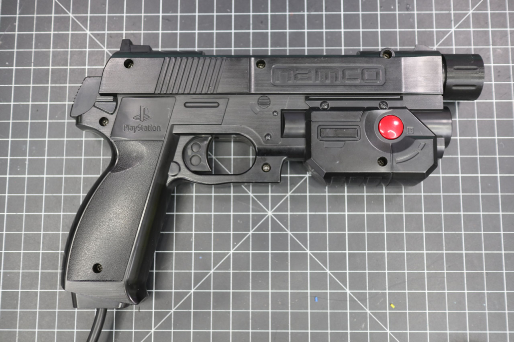
41 Put it Together
- If you have installed the lens holder screw it down until snug, you will have to align the camera in Blamcon ARC before playing
- Reinsert the screws, the small screw goes into the trigger guard
- Tighten screws until snug, do not overtighten!
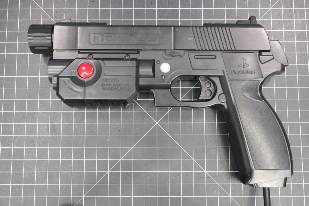
42 All Done
- Your Blamcon converted GunCon45 is ready to play! You just need to algin the camera in ARC
- The first time plugging in do not plug in the 12V, make sure the USB wiring is correct and working first.