






Some guns have a compensator, this one is the over-compensator! I won’t ask what inspired the design but you will be inspired to take down all the bad guys with this one. Working slide recoil gives that satisfying ‘clack’ as your enemies go down. This also features the two option buttons and RGB LED in all Blamcons. Note that these movie replicas are works of love and will only be offered as free 3D printable files for you to build.
Features:
- Trigger and A/B buttons
- Rumble
- Recoil with working slider action
- RGB LED
- GX-16 swappable connection
Use the model browser to highlight any parts and see where they fit in the Autocop.
Use the explode model to see how it fits together.
Build Guide
Source parts yourself or buy a complete kit (or even a ready to go Autocop), build your way! If you do build yourself the parts list below are from vendors we have used. Some links are affiliate and help support Blamcon.
Individual Parts List
Parts list for the Phazer, links are clickable and go to the last known quality vendor of that part. If a link is broken please let me know on Discord.
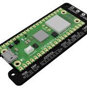 Blamcon CoreBuy
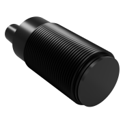 SEN0158 CameraBuy
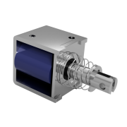 JF-0826B SolenoidBuy
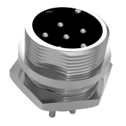 GX16 ConnectorBuy
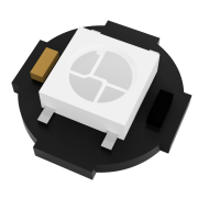 Neopixel LEDBuy
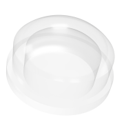 Neopixel DiffuserBuy(Printable one included in download files)
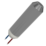 7mm Rumble MotorBuy
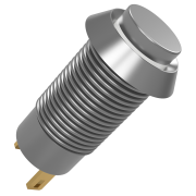 8mm button X 2Buy
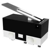 Mini MicroswitchBuy
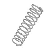 4x15x.3 SpringBuy
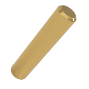 2x12mm Metal RodBuy
- 4x19mm Metal RodBuy
 4x8x.5 Washer X 2Buy
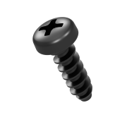 Pan Head ScrewsBuyM2x5 X 4
M3X10 X 4
M4X16 X 1
M4X20 X 2
M4X25 X 4
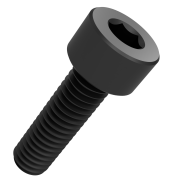 M3 X 25 Cap Head ScrewBuy
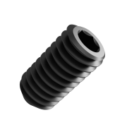 M4X6 Grub Screws X 5Buy
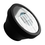 Fisheye LensBuy
Wire Lengths
Step by Step Instructions
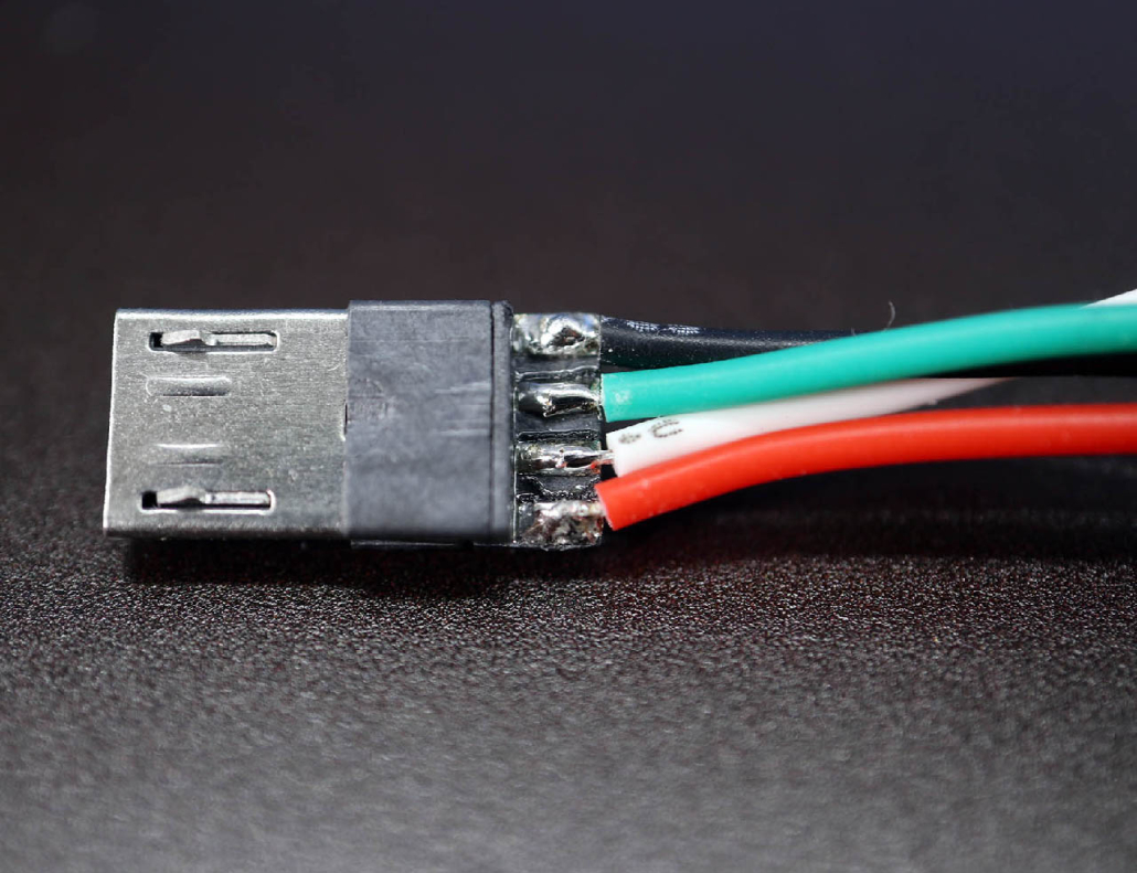
PARTS
- 40mm Red/White/Green/Black wires
- USB connector
STEPS
- Tin both ends of the wires by adding a little solder to the wires.
- Tin the USB connector by adding a bit of solder to the contacts, you only need a small amount!
- With the USB connector facing solder side up solder each wire by touching the tinned contacts together first then adding heat.
- Check carefully for bridging!
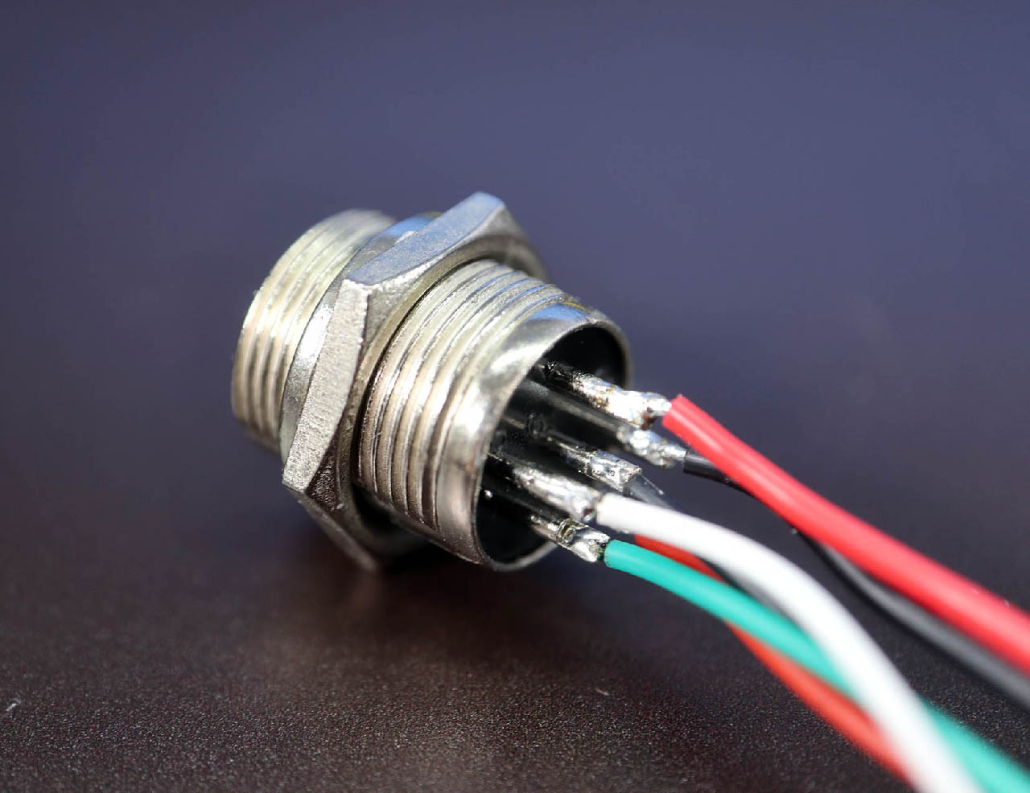
PARTS
- Soldered USB connector
- GX 16 – 6 Connector
- 120mm 22ga two strand wire
STEPS
- Tin one side of the 22 ga wires
- Tin all 6 GX 16 connectors by placing the solder in the channel and adding heat Solder the wires by touching the tinned end of the wires to the tinned contacts, get the wires in the channel for the best fit.
- Solder: 26ga red: 1, 26ga black: 3, USB red: 3, USB green: 4, USB white: 5, USB black: 6
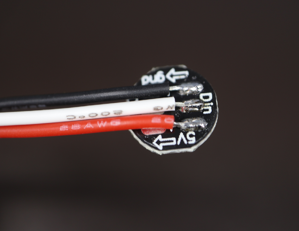
PARTS
- Neopixel LED
- 50mm Red wire, 50mm White wire, 50mm Black wire
STEPS
- Tin the three Din pads on the LED, be careful not to bridge them
- Tin one end of each of the three wires
- Touch each wire in turn to the tinned pad and apply heat, they should join very easily.
- Check again for bridging! And make sure you’re soldering to Din and not Dout
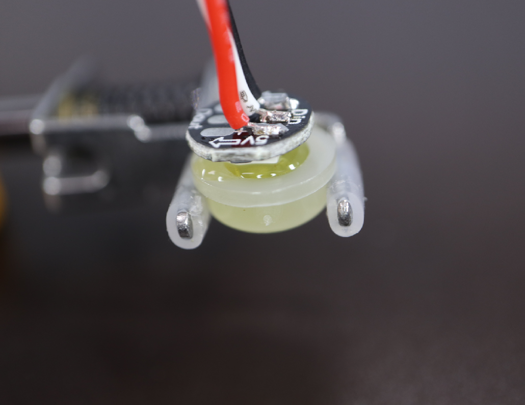
PARTS
- Soldered Neopixel LED
- LED Diffuser
STEPS
- Wear gloves, trust me on this one.
- Secure the LED diffuser in a clamp or double tape to a surface.
- Fill the Diffuser with hot glue, make sure it’s bulging out the top.
- Quickly place the LED in the hot glue, it will fit perfectly and should squish the glue out.
- Remove the excess glue around the edge.
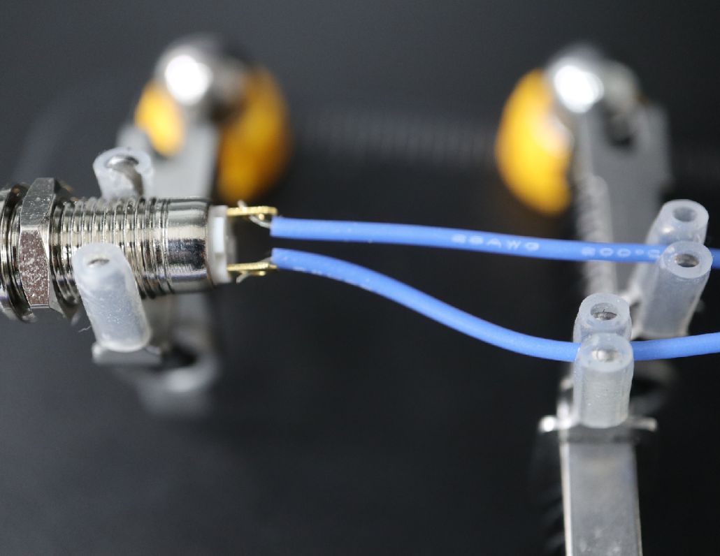
PARTS
- 8mm metal button
- 75mm Blue wire X 2
STEPS
- Stick the wires through the holes and solder in place.
Note: Do NOT hold the iron on the poles too long, the B button housing is plastic and if you melt it it may stop working. If you add heat quickly it won’t be a problem.
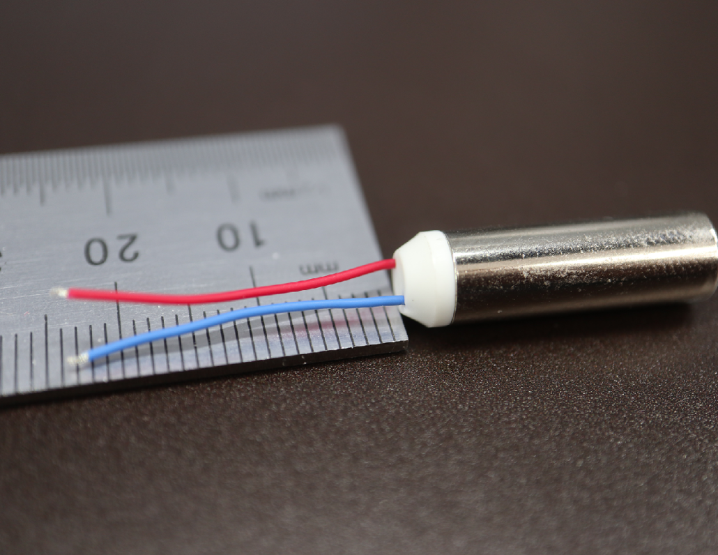
PARTS
- 7mm Rumble Motor
STEPS
- Measure 24mm from the base and cut the wires, you can go longer if you want to but this is the min
- Carefully strip 2mm at the ends
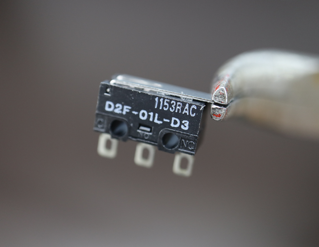
PARTS
- Mini Microswitch
STEPS
- Close the microswitch, when you do so a small amount of the leaf will stick out.
- Grab that with pliers and bend it by opening the switch and pushing down on the main part of the leaf with a finger right at the point it goes into the pliers. This keeps pressure off the pivot of the switch and creates a sharp bend.
- See step 8 for result.
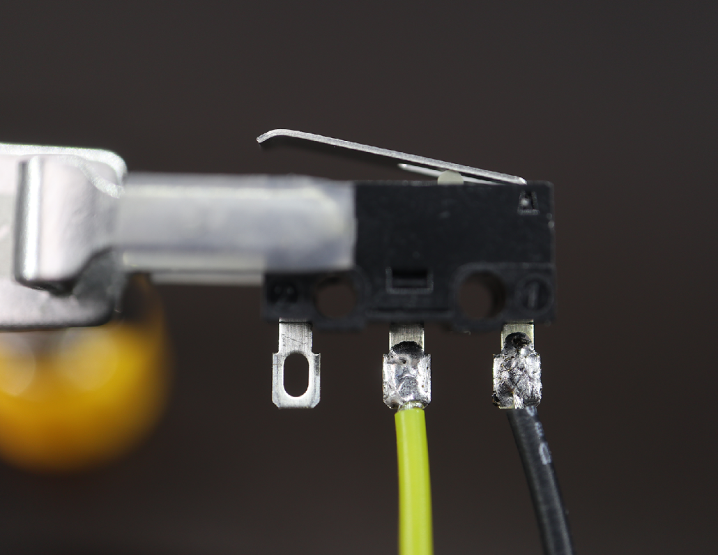
PARTS
- Mini Microswitch 130mm Yellow wire
- 140mm Black wire
STEPS
- Solder the black wire to the common pin where the metal leaf connects to the switch.
- Solder the yellow wire to the middle pin, which is normally open.
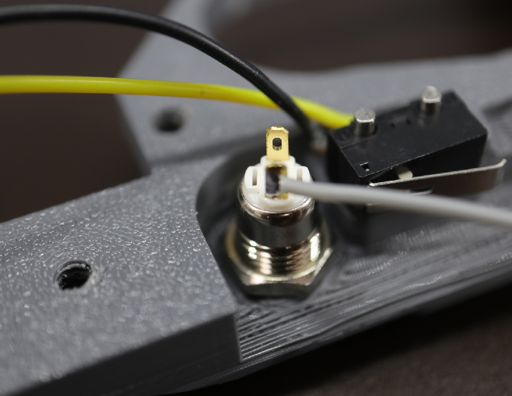
PARTS
- Blamcon_Auto9_BodyLeft_V1
- 8mm metal button
- 120mm Gray wire
- Soldered Trigger switch
- 12mm X 2mm metal rods
STEPS
- Insert the A button into the hole on Blamcon_Auto9_BodyLeft_V1 and screw on nut, spinning the switch is easier at the end
- Install the mini microswitch on the 2mm rods through the holes in the frame (If you are using an Omron microswitch bend the connectors down so they won’t get pinched in the frame)
- Solder the gray wire to the A button on the pole that’s furthest from where the trigger switch will go
STEPS
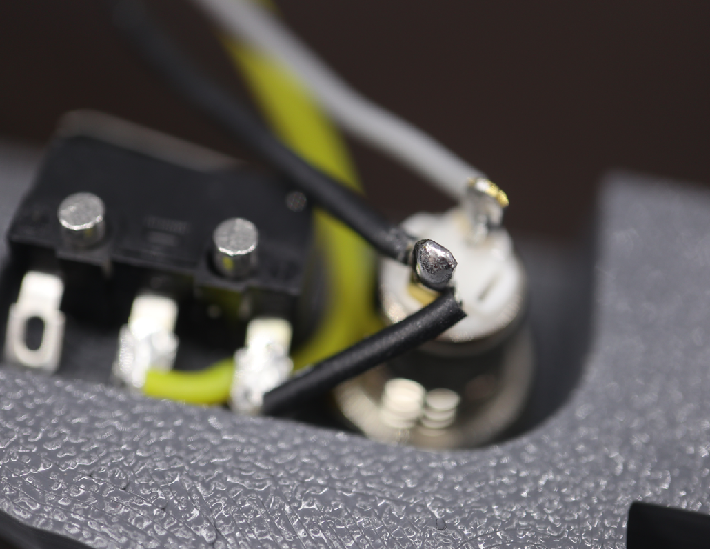
- Run the black wire to the A button and make a nick in the wire where it touches the contact on the A button, pull the nick to expose the wire.
- Solder the black wire and gray wire to the A button.
PARTS
- SEN0158 IR Positioning Camera
STEPS
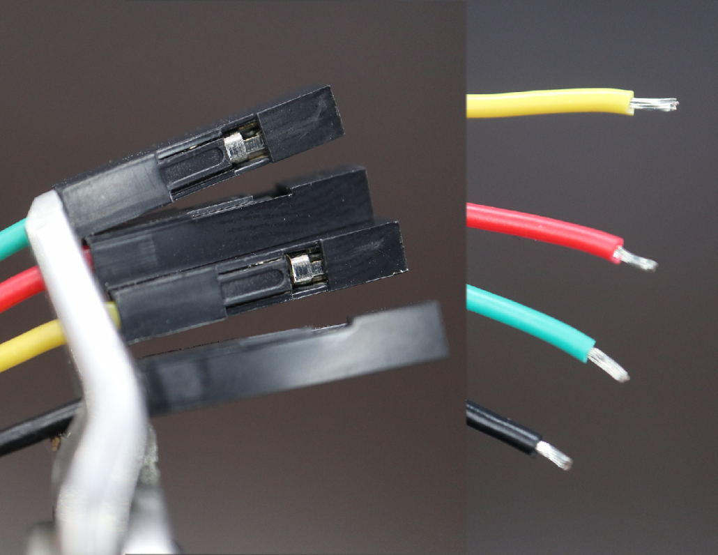
- Cut the connectors off the camera flush, you will need all the wire.
- Strip the camera wires at least 3mm
PARTS
- Solenoid
STEPS
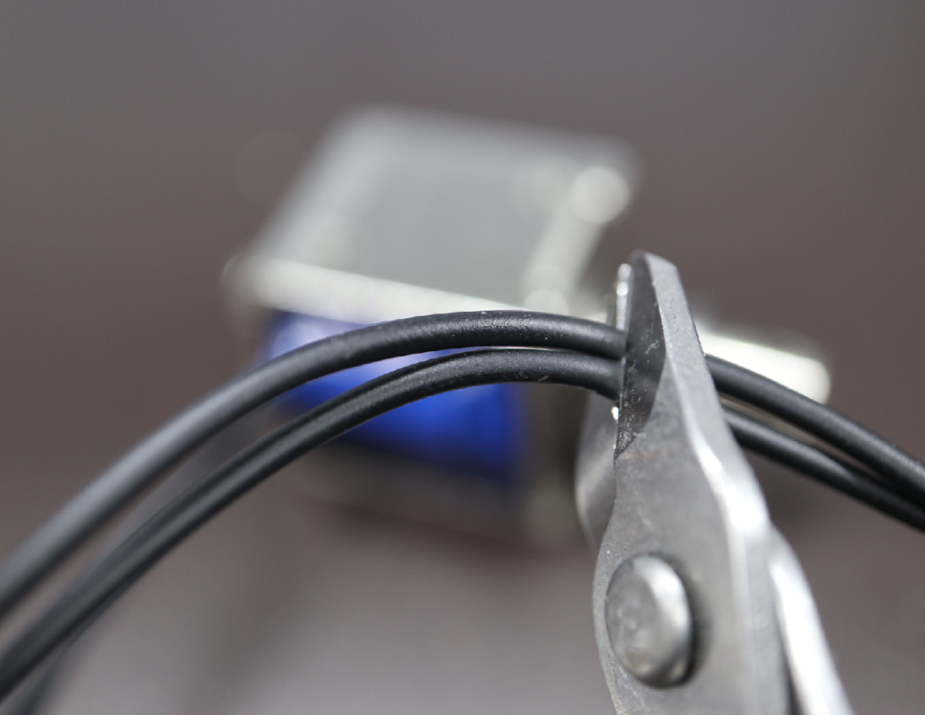
- Measure 11CM of wire starting from the side of the solenoid and cut to length.
- Strip 4mm off the ends.
PARTS
- SEN0158 IR Positioning Camera
STEPS
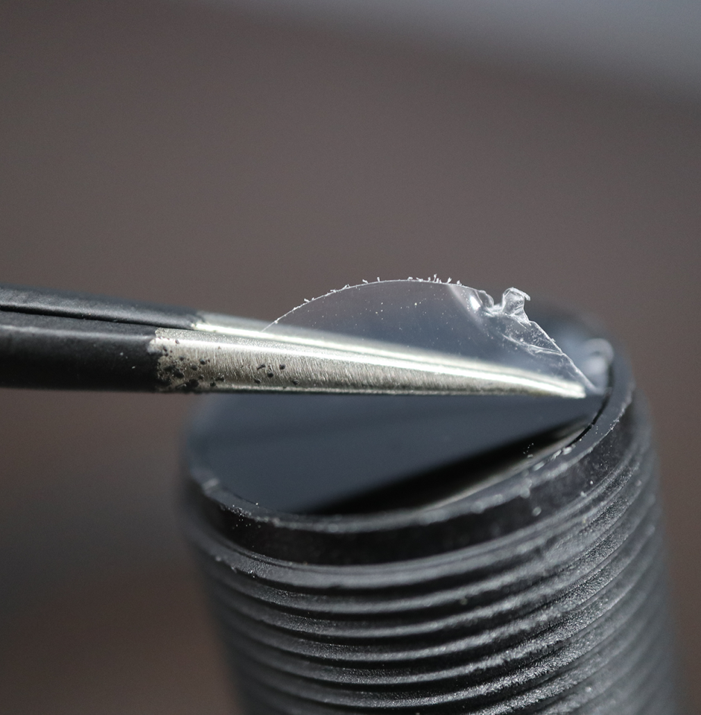
- CAREFULLY peel the protective film off the camera lens, failing to do so may result in poor tracking
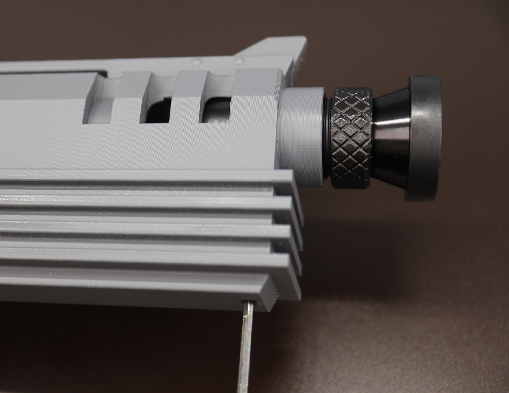
PARTS
- Blamcon_Auto9_Front_V1
- SEN0158 IR Positioning Camera
- M4x6mm Grub Screw
- Lens Adapter (Optional)
STEPS
- If you are going to install a lens adapter screw it on to the lens first then screw onto the camera until flush, do not overtighten
- Screw the M4 grub screw until it comes into the barrel area, back it out until it’s recessed
- Insert the camera into the barrel with the LED facing to the left side to orient correctly
- Lightly tighten the grub screw until it holds the barrel in place, you will need to use this to center the camera before you play
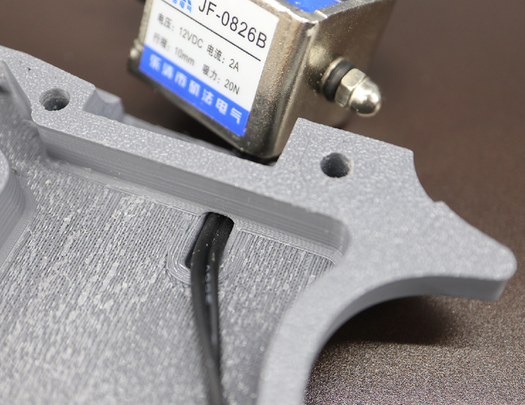
PARTS
- Blamcon_Auto9_BodyRight_V1
Solenoid
Blamcon Core
STEPS
- Insert the solenoid through the hole in Blamcon_Auto9_BodyRight_V1
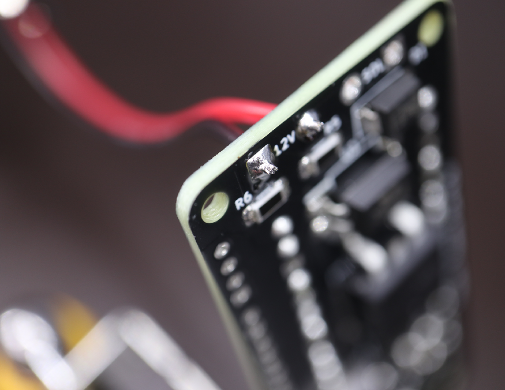
PARTS
- Blamcon Core
- Soldered GX-16 Connector
STEPS
- Solder the red wire to the round 12V positive input hole
- Solder the black wire to the square 12V ground input hole
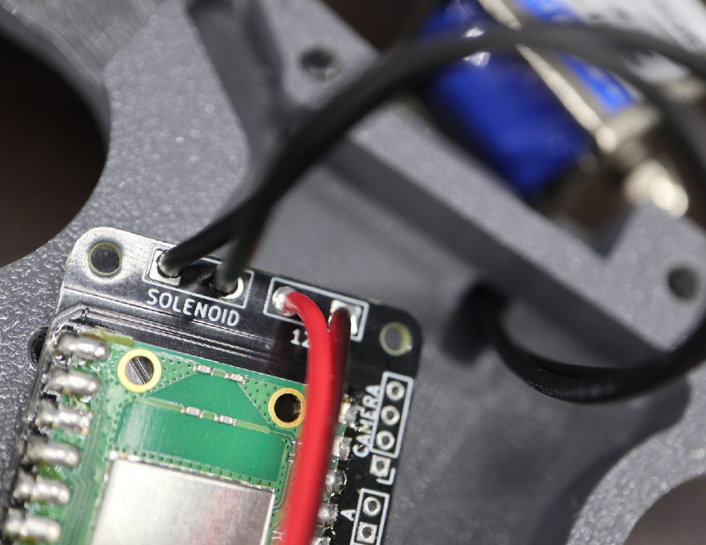
STEPS
- Solder the solenoid to the SOLENOID holes in the core, polarity doesn’t matter
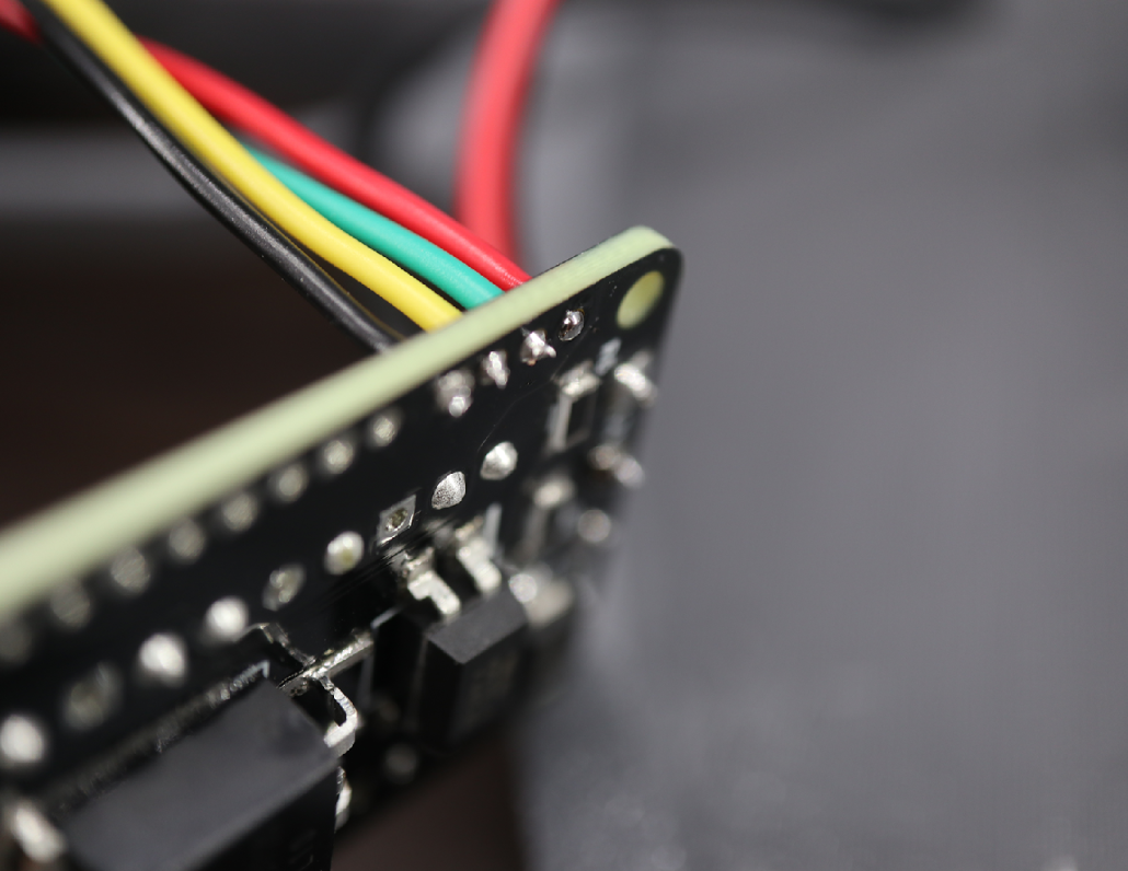
PARTS
- SEN0158 Camera installed into the front
STEPS
- Solder the black wire to the square camera connector hole
- Solder the yellow wire to the connector hole beside the black wire
- Solder the green wire next connector hole beside the yellow
- Solder the red wire to the first camera connector hole
- From the top it should go: red, green, yellow, black (with black being in the square hole)
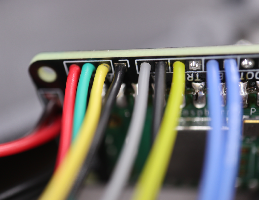
PARTS
- Blamcon Core
- Wired A/B/Trigger Buttons
STEPS
- Solder the yellow trigger wire to the round trigger hole.
- Solder the gray A button to the round A hole.
- Solder the black shared A/Trigger wire to the square A hole.
- Solder the blue B wires to either of the B holes
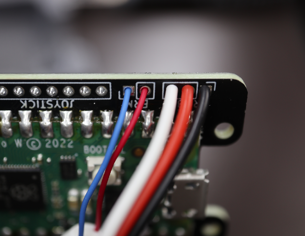
PARTS
- Soldered LED
- Prepared Rumble motor
STEPS
- Solder the Black LED wire to the square LED connector hole
- Solder the Red LED wire to the middle positive LED connector hole
- Solder the White LED wire to the end round signal connector hole
- Solder the blue rumble motor wire to the square ground connector hole
- Solder the red rumble motor to the round positive connector hole
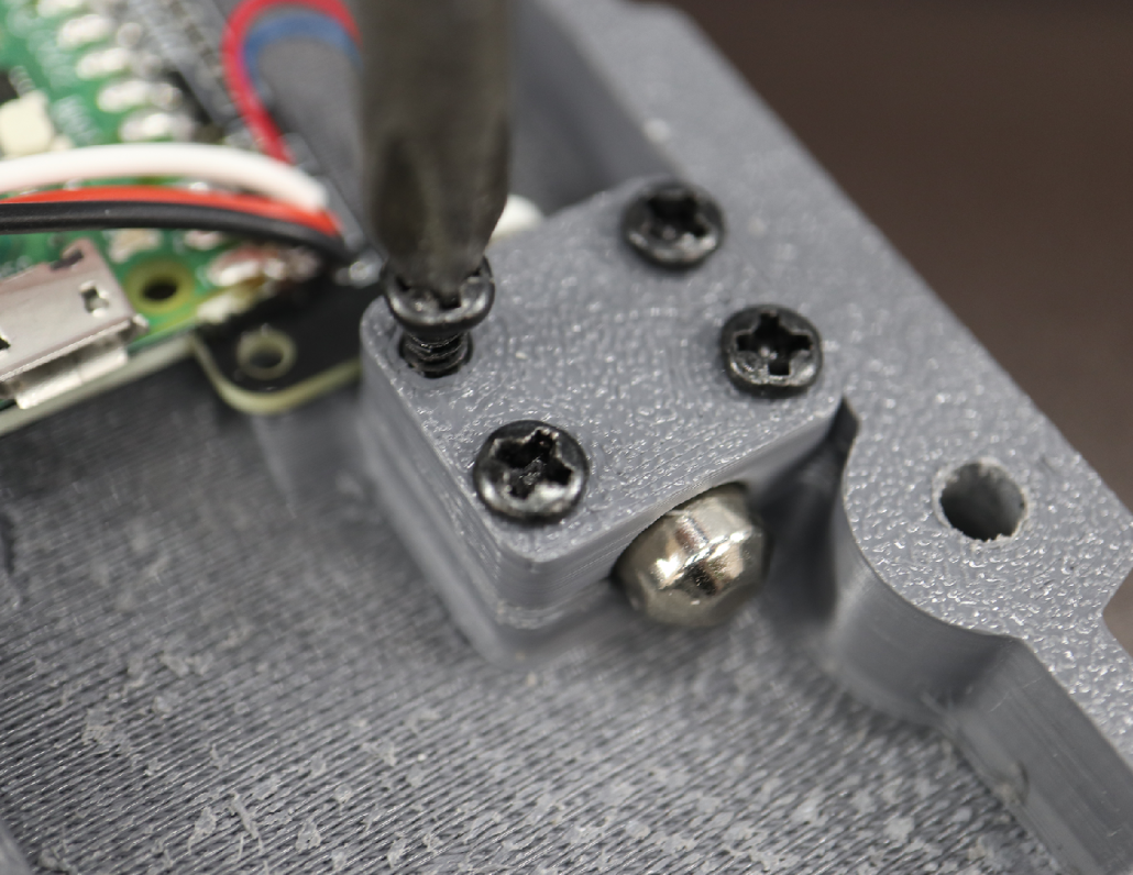
PARTS
- Blamcon_Auto9_RumbleCover
- Pan Head M3X10 X 4 screws
- Soldered Rumble Motor
STEPS
- Screw rumble motor in place using the Blamcon_Auto9_RumbleCover and 4 pan head screws
Note: If it’s loose you can add a bit of tape as a spacer
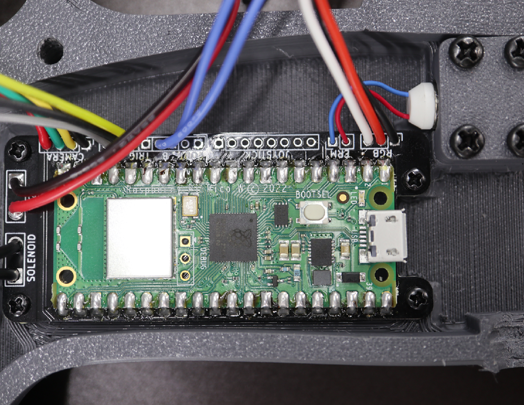
PARTS
- Blamcon Core
- Pan Head M2x5
STEPS
- Screw the core in place with the pan head screws, do not overtighten!
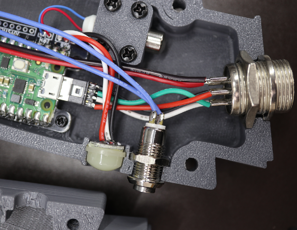
PARTS
- Soldered B button
- Soldered and glued LED
- Soldered GX16
STEPS
- Loosen the nut on the GX16 until it sits in the track easily.
- Tighten the GX16 by 30 deg turns until it fits tights, then back off until just barely loose.
- Optionally, add threadlocker to keep it in place without it may move over time.
- Set the B and LED into the tracks. Tighten the B nut in the same way as the GX16 nut.
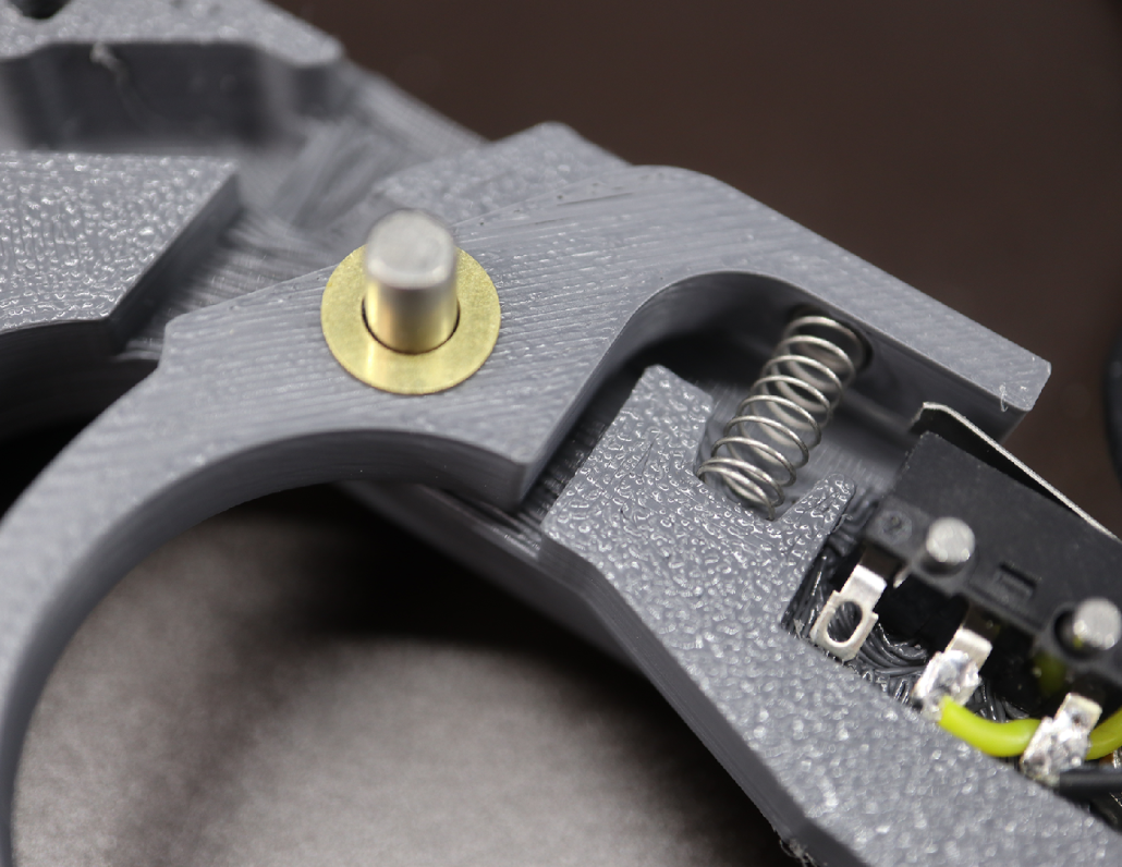
PARTS
- 4X10mm Spring
- 4mmX18mm Brass Rod
- 8x4x.5mm Brass Washer
STEPS
- Insert the 4mm rod into the trigger hole, then add a brass washer
- Insert the trigger onto the rod, make sure it moves smoothly, if not trim until it moves smooth but tight
- Add a brass washer onto the rod, so there should be a washer now on each side of the trigger
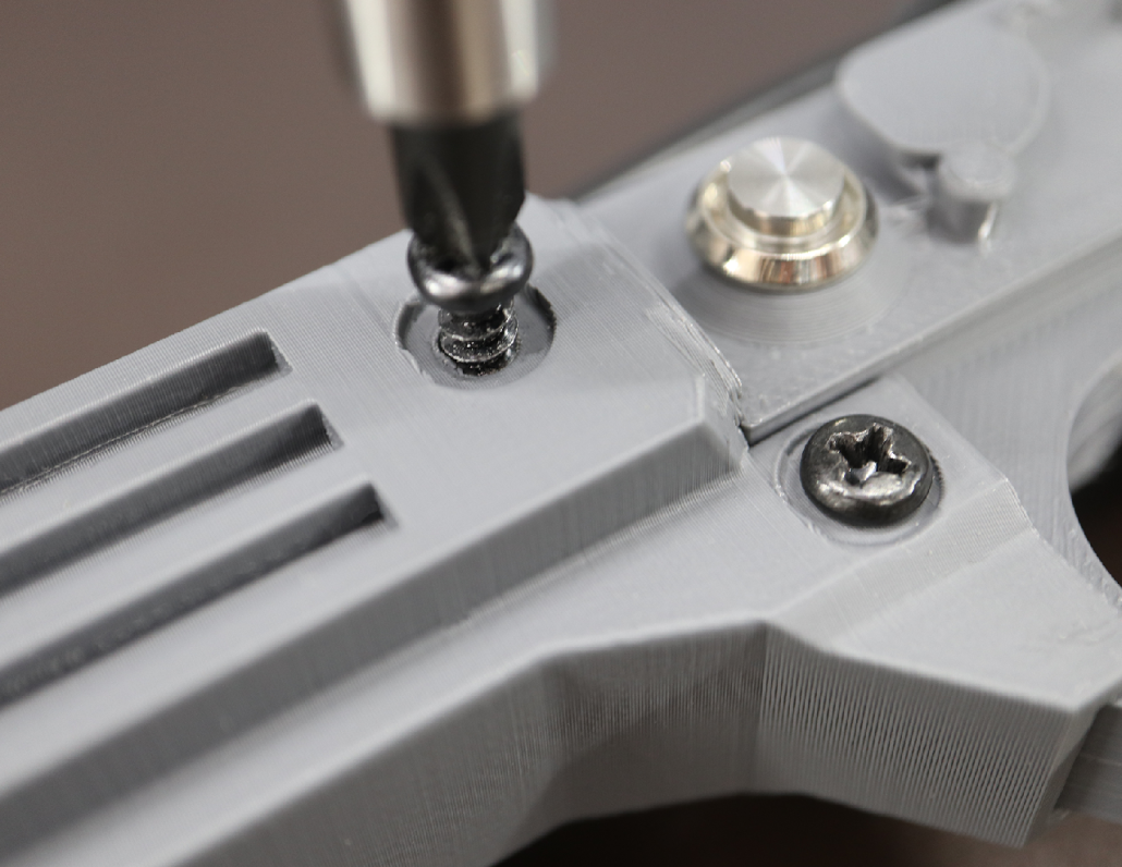
PARTS
- M4X25 Pan Head Screw
- M4X15 Pan Head Screw
STEPS
- Insert the front into the V groove in the frame
- Make sure the holes line up and there’s no support material or obstruction
- Screw the 24mm screw into the top hole, and the 16mm screw into the bottom hole
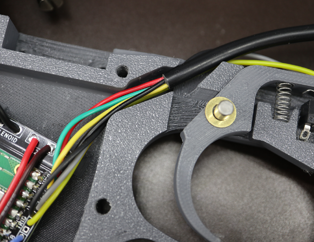
STEPS
- Place the button wires into the wire guide first
- Place the Camera wire on top of the button wires
- Pull the wires back until there is no slack in the top where they are exposed, you don’t want them to rub against the slide
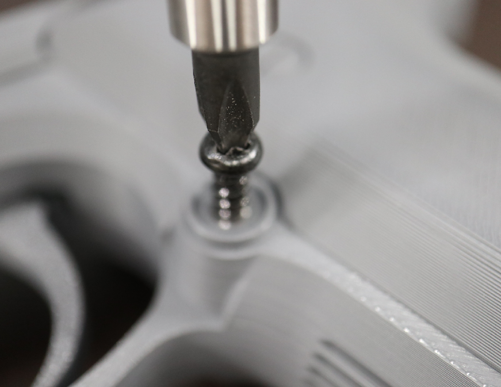
PARTS
- M4X25 Pan Head Screw
STEPS
- Screw the 25mm screw in to join the frame
- This is the best time to check for wire pinches, gaps or other issues and resolve them, it should fit together with no gaps
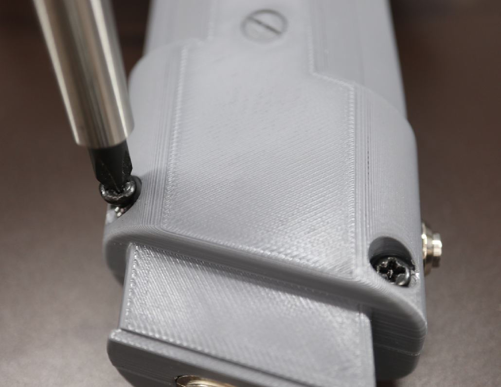
PARTS
- M4X18 Pan Head
- M4X20 Pan Head
STEPS
- Screw the 18mm screw into the bottom front hole of the grip
- Screw the 20mm screw into the bottom back hole of the grip
Note: Do not get these confused or you may cause a bulge in the frame
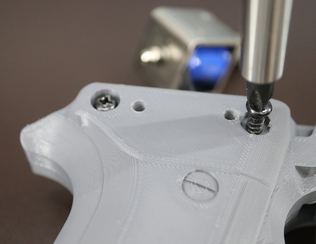
PARTS
- Pan Head M4X 25mm X2
STEPS
- Screw the pan head screws in until the two halves of the frame is flush, be careful not to pinch the wires
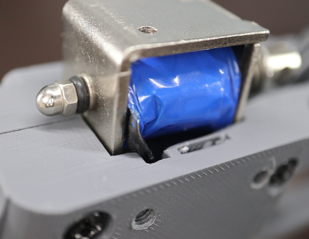
PARTS
- Solenoid
STEPS
- Install the solenoid as shown
- Push the wires into place in the plastic until they match the picture, you don’t want them rubbing against the frame
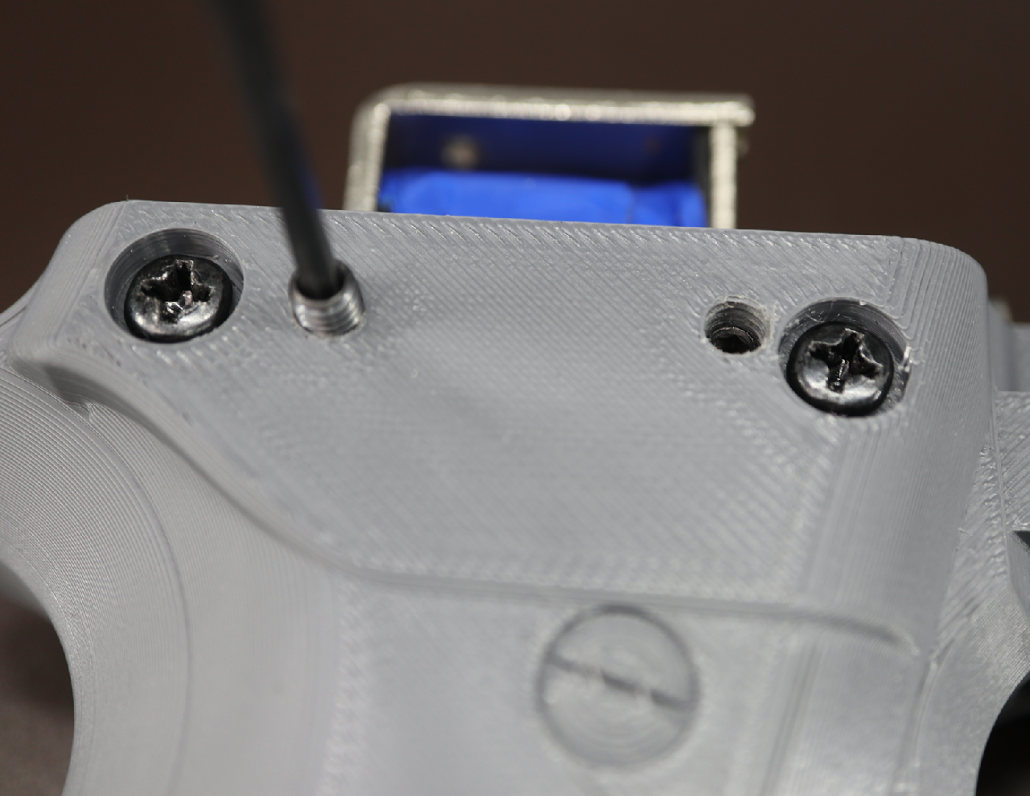
PARTS
- M4X6 Grub Screw X4
STEPS
- If you have an M4 tap, tapping these hole helps a lot
- If you are not tapping, run the set screw in slowly, with the solenoid out, backing them out every turn or so. Go all the way through into where the solenoid is, then back them all the way out again. You want to cut these grooves smoothly.
- With the solenoid in place, run the 4 set screws until they juuust touch the solenoid, do not tighten.
Note: Set screw have very little material between the head and body, applying too much force can cause the head to bulge out, jamming it. You really gotta try to do this but it has been done.
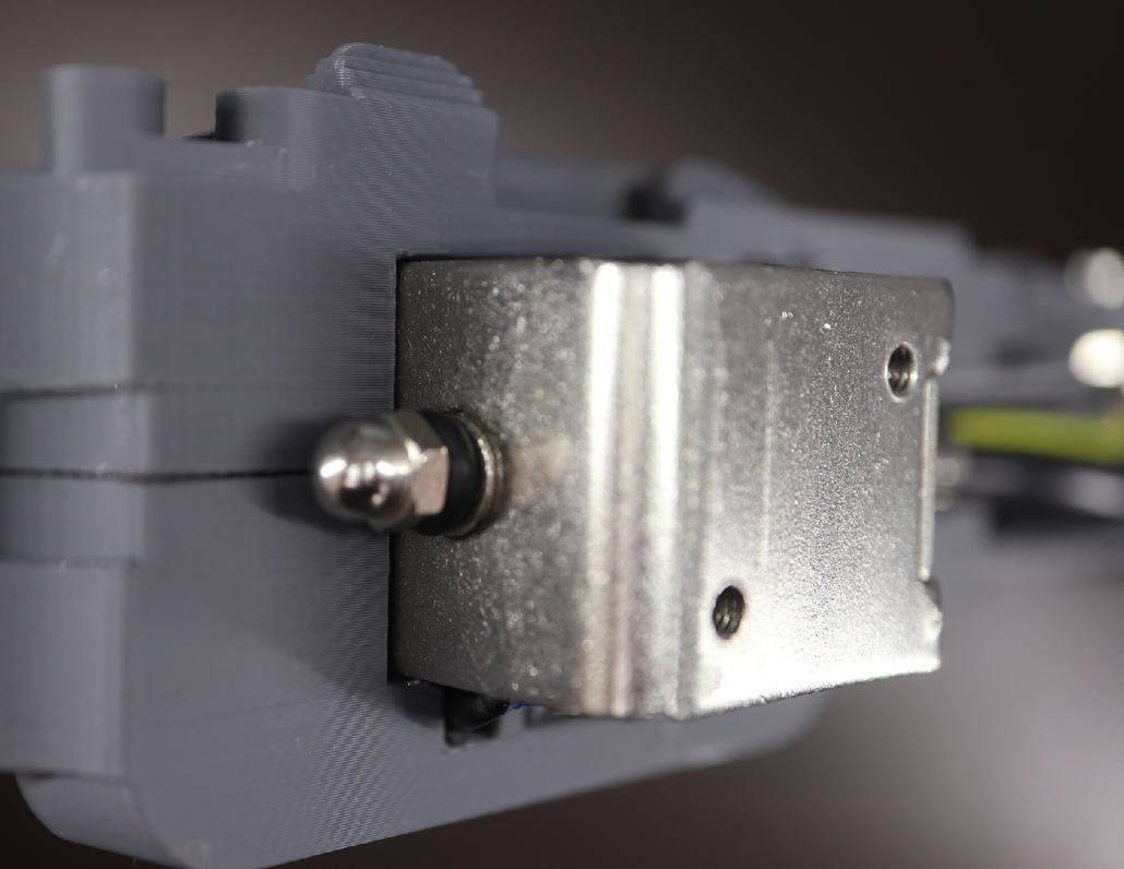
STEPS
- Looking from this angle, align solenoid using the set screws until they center the solenoid
- Lightly tighten, do not overtighten, it will stay in place
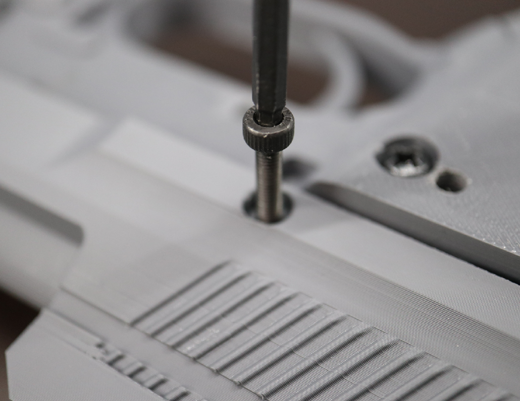
PARTS
- M3X25 cap head screw
STEPS
- Align the solenoid actuator hole into it is level with this hole
- Run the cap head screw though the hole in the solenoid actuator until it’s all the way in
- Move the slide, it should move very freely, if need be adjust the set screws by backing one side off a quarter turn then tightening the opposite a quarter turn, do until the slide moves freely

You’re all done! Check out our getting started guide and start having fun.
(Double-click on manual for full screen view)
The M3F files are in the correct print orientation and organized by tray. They will open in Orca Slicer as trays you can slice with your own settings and printer.
The Gcode files are ready to print for the printers listed, they are set up for PLA at .16. They print slow and strong and these are the same print settings we use. We print with Matter3D Performance PLA but should work with any decent PLA, print at your own risk.
All Blamcon models are released under the Creative Commons – Attribution – Non-Commercial – No Derivatives license. By downloading models from Props3D you are agreeing to abide by these terms.