
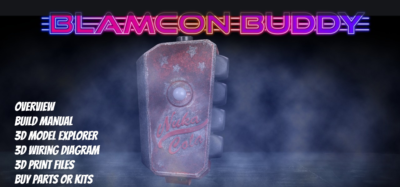


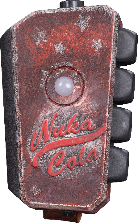


The Blamcon Buddy is the bestest of pals for any one handed Blamcon. It lets you assign up to 5 buttons to use with your off hand. No more holding pistols awkwardly with 2 hands while you play just so you can hit that grenade button, use your grenade hand like the universe intended!
Features:
- Wireless, binds directly to your Blamcon
- 5 assignable buttons
- LED
- Rechargable via USB C
Use the model browser to highlight any parts and see where they fit in the Blamcon Buddy.
Use the explode model to see how it fits together.
Source parts yourself or buy a complete kit (or even a ready to go Buddy), build your way! If you do build yourself the parts list below are from vendors we have used. Some links are affiliate and help support Blamcon.
Individual Parts List
Parts list for the Buddy, links are clickable and go to the last known quality vendor of that part. If a link is broken please let me know on Discord.
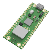 Raspberry Pi Pico W
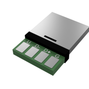 Micro USB ConnectorBuy
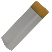 3.7v 550ma lipo BatteryBuy
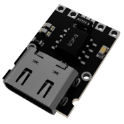 TP4057 Charging ModuleBuy
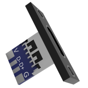 USB-C PortBuy
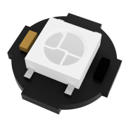 Neopixel LEDBuy
 10mm LED Diffuser (Printable)Buy
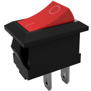 10x15 Toggle SwitchBuy
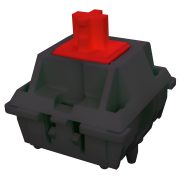 MX Keyswitch X 4
 Black Keycap (Printable)Buy
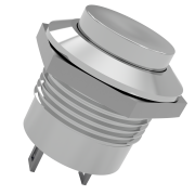 16mm Push Button MetalBuy
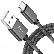 USB C CableBuy
- Leather Strap (19mmX210mm) (Printable)
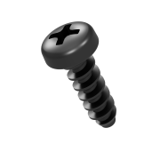 Pan Head M2x5 X 4Buy
- Pan Head M4x10 X 2Buy
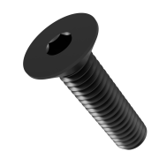 Flat Head Self Tapping M4x12 X 4Buy
| 28ga | Length(mm) | Use |
| Black | 40 | USB-Charger |
| 30 | Charger-Pico | |
| 30 | LED Gnd | |
| 140 | Buttons Gnd | |
| Red | 20 | USB-Charger Pos |
| 30 | Charger-Switch Pos | |
| 30 | Switch-Pico Pos | |
| 35 | LED Pos | |
| Yellow | 55 | Button 1 Trigger |
| Green | 30 | USB Data Pos |
| 55 | Button 4 Selector | |
| Blue | 55 | Button 3 B |
| Brown | 55 | Thumb Foot Pedal |
| Gray | 55 | Button 2 A |
| White | 30 | USB Data – |
| 30 | LED Data |
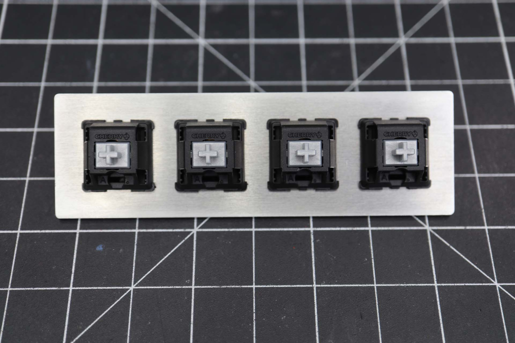
PARTS
- BlamconBuddy_Plate_V1 (or metal plate)
- MX Keyswitch X 4
STEPS
- Snap the key switches into the plate in the orientation shown
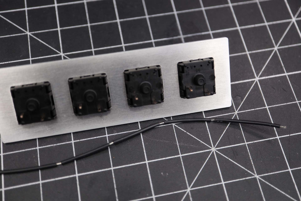
PARTS
- 140mm Black wire
STEPS
- Make a nick on the black wire 30mm down and align with the bottom pin on the first MX switch
- Nick and separate the wires at the intervals of the bottom pin of the other three key switches
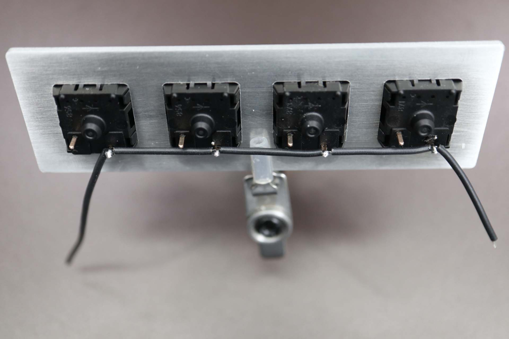
STEPS
- Solder the black wire to the bottom pin of each key switch
PARTS
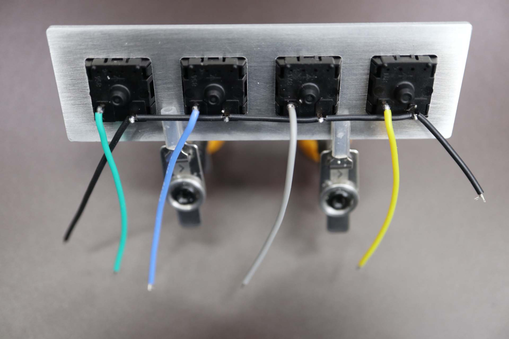
- 55mm Yellow Wire
- 55mm Gray Wire
- 55mm Blue Wire
- 55mm Green Wire
STEPS
- Solder the yellow wire to the top switch
- Solder the gray wire to the second switch
- Solder the blue wire to the third switch
- Solder the green wire to the last switch
PARTS
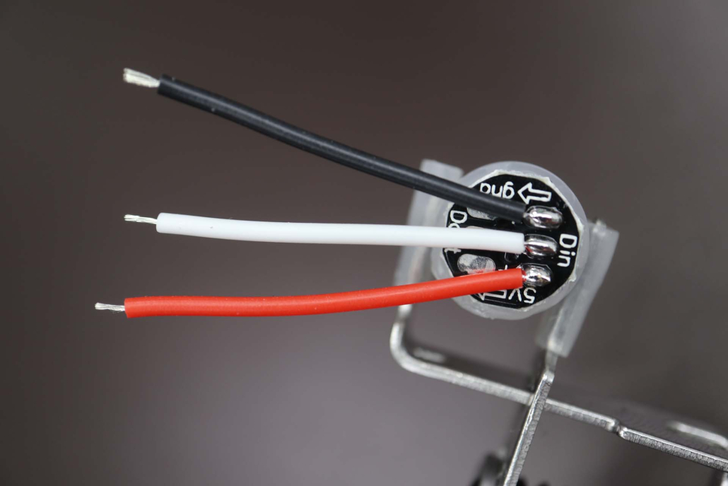
- Neopixel LED
- 10mm LED Diffuser (Printable)
- 30mm Black Wire
- 30mm White Wire
- 35mm Red Wire
STEPS
- Glue the Diffuser to the LED by filling the diffuser with hot glue and inserting the LED, be careful and wear gloves!
- Solder the Black wire to the Gnd IN pad (Din side)
- Solder the White wire to the Din Pad
- Solder the Red wire to the 5V IN pad (Din side)
PARTS
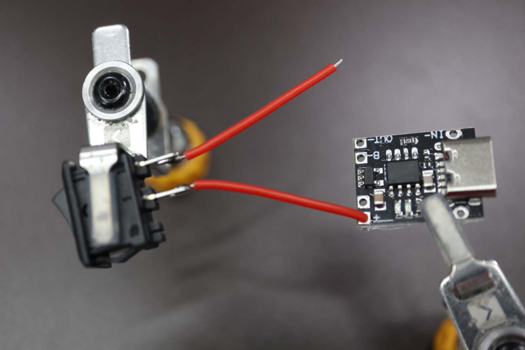
- TP4057 Charging Module
- 10×15 Toggle Switch
- 30mm Red Wire
- 30mm Black Wire
STEPS
- Solder a 30mm red wire to the IN+ on the charging module
- Solder a30mm black wire to the Out- on the charging module
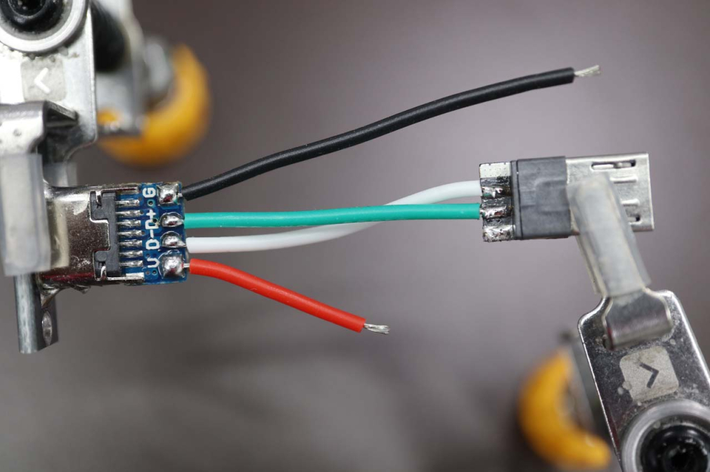
PARTS
- USB C Port
- Micro USB Connector
- 20mm red wire
- 30mm white wire
- 30mm green wire
- 40mm black wire
STEPS
- Solder the 20mm red wire to the V pad of the USB C Port
- Solder the 30mm white wire to the D- pad of the USB C Port and the Micro USB port
- Solder the 30mm green wire to the D+ pad of the USB C Port and the Micro USB port
- Solder the 30mm black wire to the G pad of the USB C Port
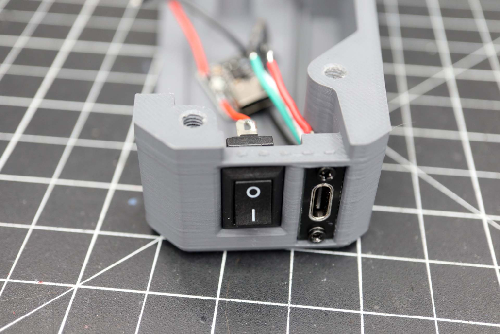
PARTS
- 2.5x5mm Pan Head Screws X2
- BlamconBuddy_BodyLeft_V1 (for right handed people, BlamconBuddy_BodyRight_V1 for left handed people)
STEPS
- Insert the 15mm switch in the orientation shown, push hard and it should click into place
- Insert the USB C port with the red wire up and screw in place with the 2.5x5mm pan head screws
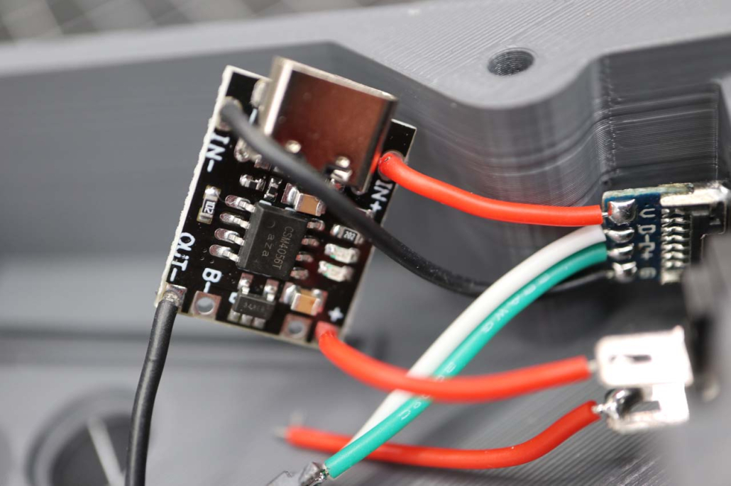
PARTS
- 30mm Red Wire X 2
STEPS
- Solder the 20mm red wire from the USB V to the charger IN+
- Solder a 30mm red wire from the bottom 15mm switch pole
- Solder the 40mm black wire on the USB C G to the charger IN-
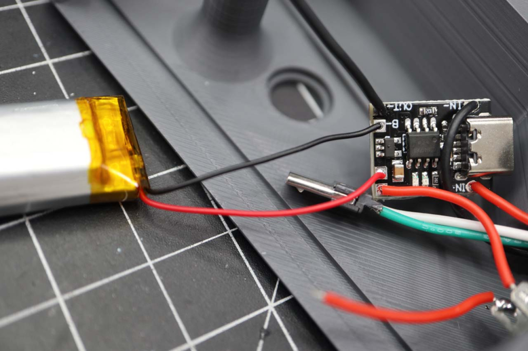
PARTS
- 3.7v 550ma lipo Battery
STEPS
- Solder the red wire from the battery to B+ on the charger
- Solder the black wire from the battery to B- on the charger
NOTE: Lipo Batteries WILL get ruined if the + and – touch, use electrical tape if needed while soldering the batteries to protect the terminals and be VERY careful you solder the wires in the correct orientation
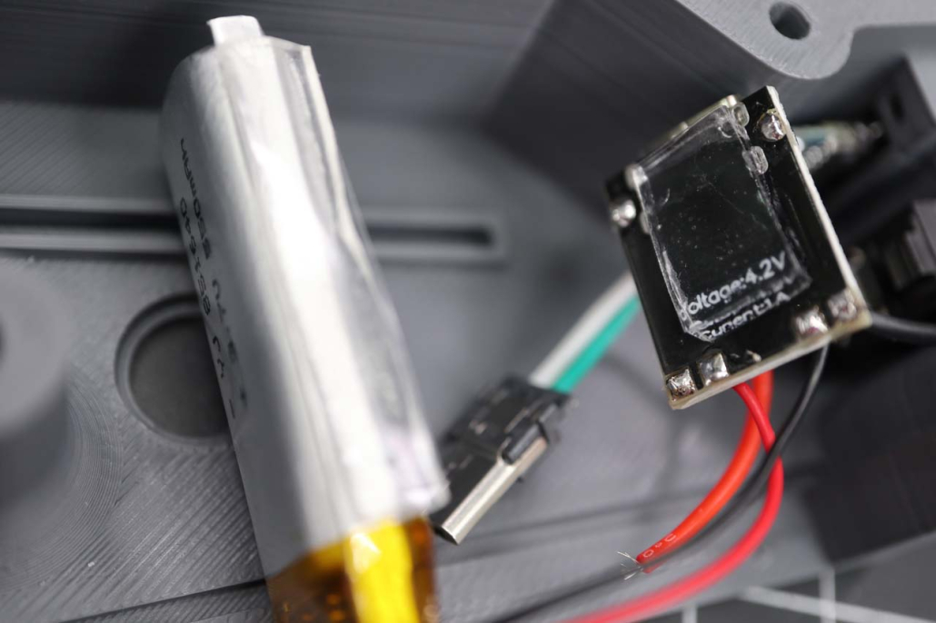
PARTS
- Double Sided Tape
STEPS
- Place double sided tape on the back of the charger and battery
Note: You don’t HAVE to do this, but it helps. You can also use hot glue if you’re VERY careful, esp with the battery
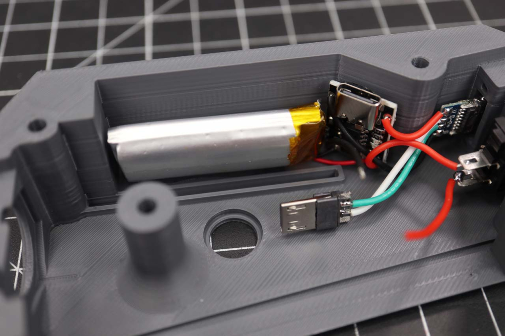
STEPS
- Using the double sided tape applied in the previous step affix the charger
Note: You don’t HAVE to do this, but it helps.
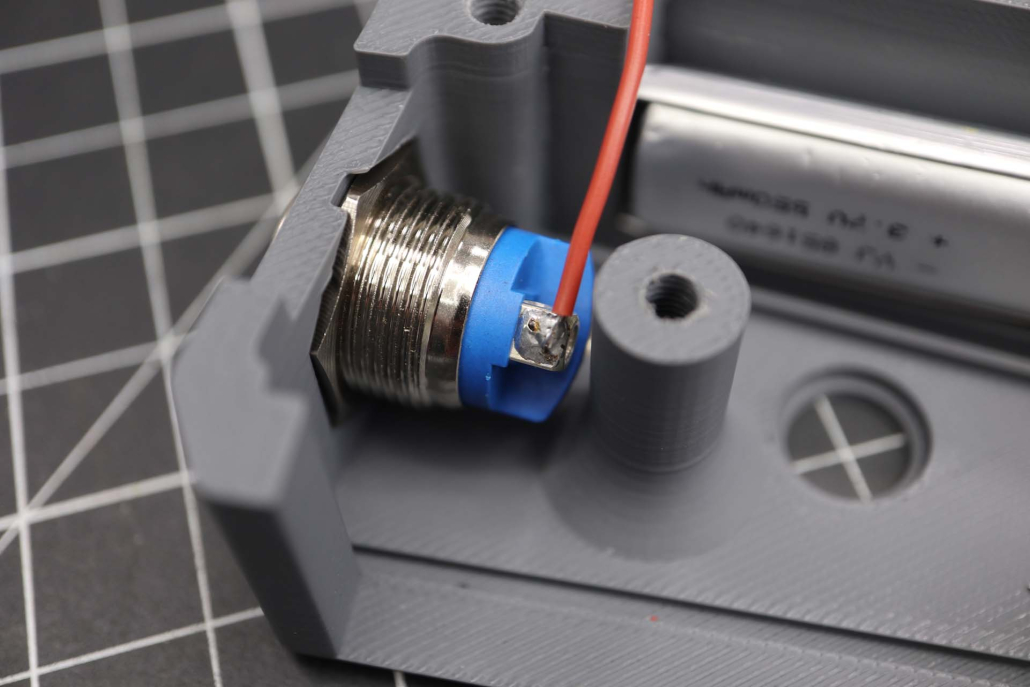
PARTS
- 16mm Push Button Metal
- 16mm button nut
- 55mm Brown Wire
STEPS
- If the button came with screws to hold the wires in place, remove them. Soldering is more reliable
- Screw in the button holding the nut in place
- Solder the 55mm brown wire to one pole on the button
Hint: If the orientation of the button is wrong you can rotate the nut in the holder until it’s correct. Tinning both poles of the switch first will make connecting wires easier. If you tin, remember to tin the wires separately too!
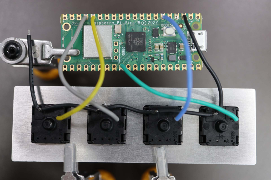
STEPS
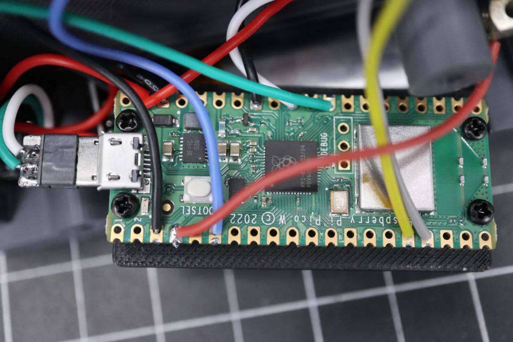
- Solder the Button 1 Yellow trigger wire to Pin 16 on the Pico
- Solder the Button 2 Gray A wire to Pin 17 on the Pico
- Solder the Button 3 Blue B wire to Pin 6 on the Pico
- Solder the Button 3 Green Selector wire to Pin 29 on the Pico
- Solder the Ground Black wire to Pin 3 on the Pico
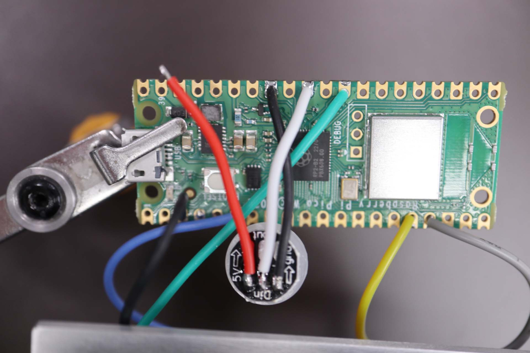
STEPS
- Solder the white LED signal wire to Pin 31 on the Pico
- Solder the black LED ground wire to Pin 33 on the Pico
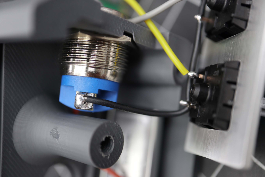
STEPS
- Solder the ground wire from the MX Keys to the 16mm thumb button
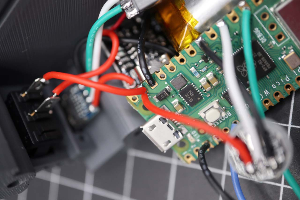
STEPS
- Solder the LED 5V and the Out + from the charging module to Pin 39 (VSYS) on the Pico
- Solder the black Out – wire from the charging module to Pin 38 (Ground) on the Pico
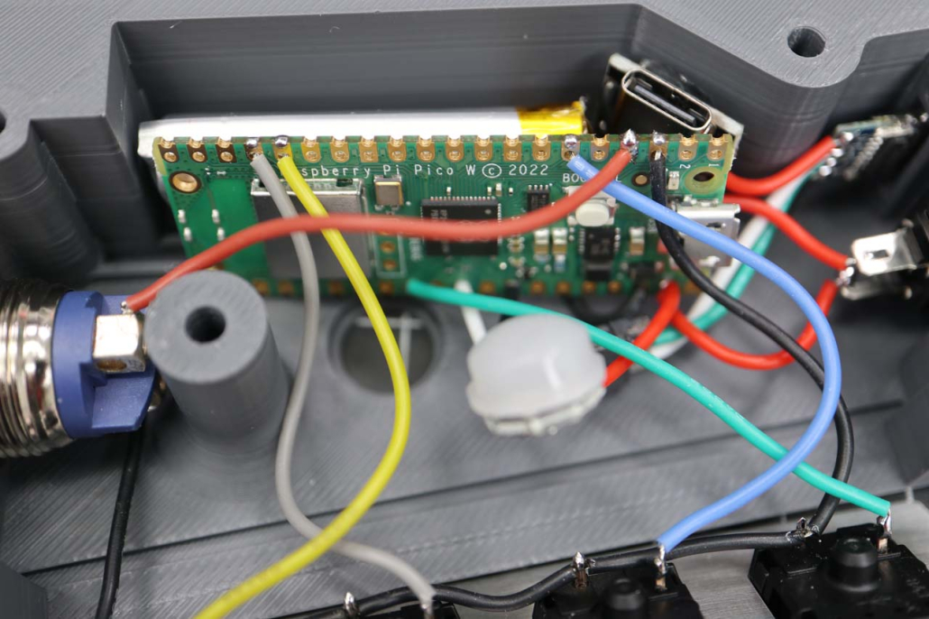
STEPS
- Solder the brown wire from the 16mm thumb button to pin 4 on the Pico
PARTS
- 2.5X5mm Pan Head Screw X4
- BlamconBuddy_PicoPlate_V1
STEPS
- Plug the Micro USB connector into the Pico, make sure it’s in snug
- Screw the pico onto the BlamconBuddy_PicoPlate_V1 using the 2.5x5mm pan head screws.
STEPS
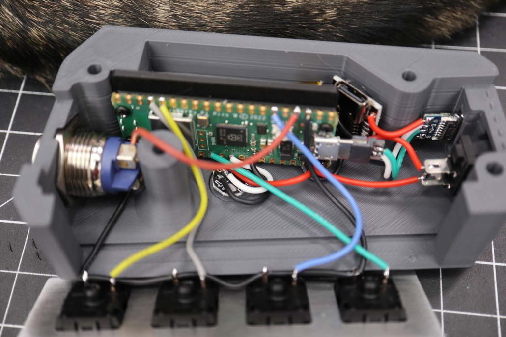
- Insert the LED into the hole, it should be very snug. If it is loose or you want to be sure it won’t fall out add hot glue to taste.
STEPS
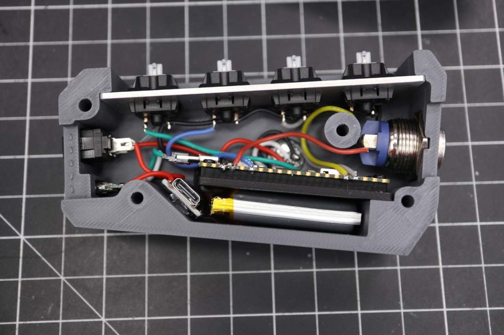
- Mount the Pico plate into its track securely
- Mount the button plate into its track securely
- Make sure the wires are secure and not blocking anything
PARTS
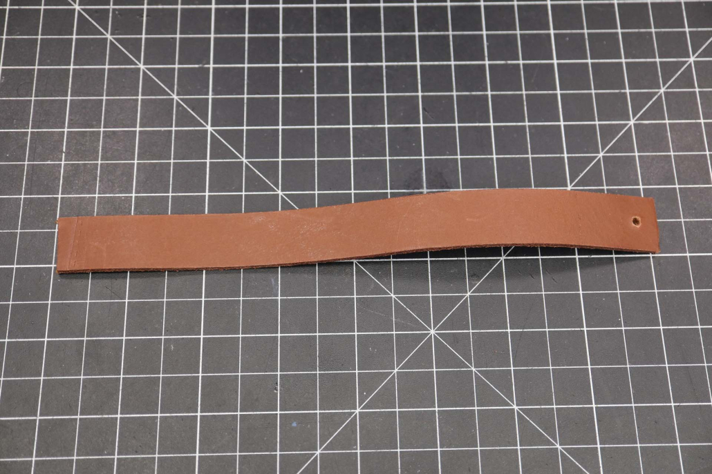
- 3/4in (19mm) leather strap 8.5in (210mm) Long OR
- BlamconBuddy_TPU_Strap_V1
STEPS
- If you are using leather drill a 4mm hole 1cm from the top of the strap, you can insert it into the buddy at the right angle and make a mark if you’re unsure of the position or print the 3D model as a reference first
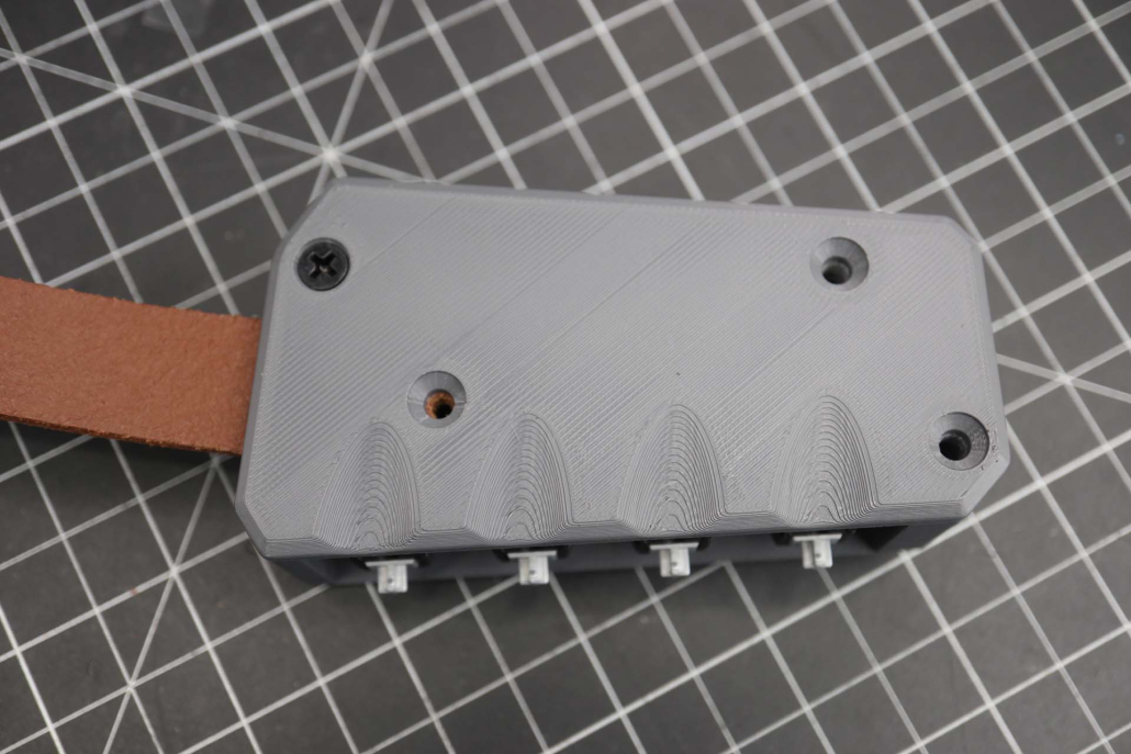
PARTS
- M4x16 Flat Head Screw X 2
- BlamconBuddy_TopLeft_V1
STEPS
- Screw the M4x16 flat head screw into the top back hole
- Insert the strap so the hole lines up
- Screw a second M4x16 flat head screw through the strap to secure it
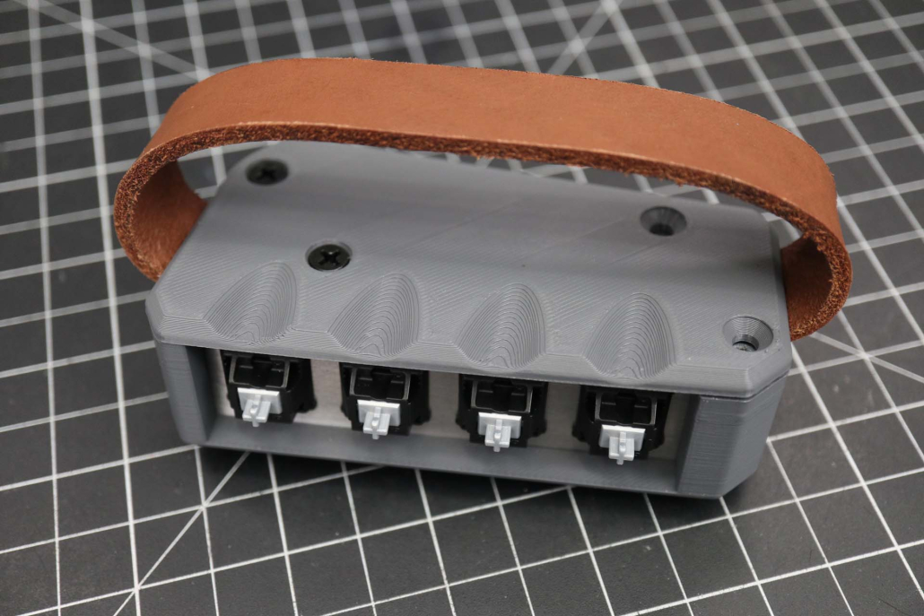
PARTS
- M4x16 Flat Head Screw X 2
STEPS
- Insert the strap into the gap on the bottom
- Srcew in the last M4x16 flat head screws to secure the plate and strap
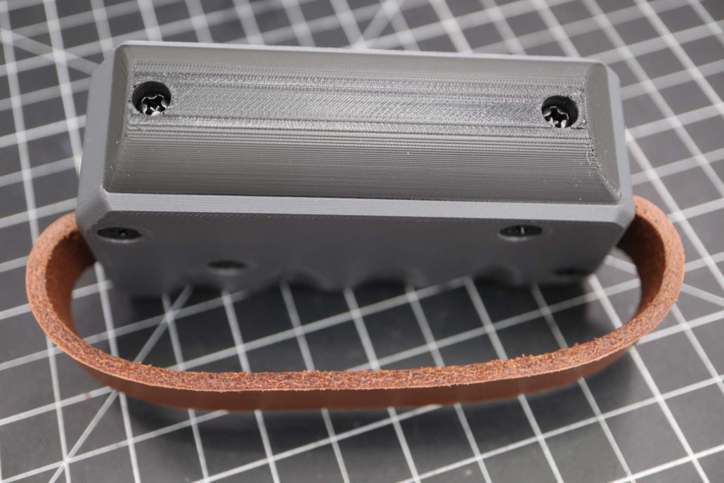
PARTS
- M4x10mm Pan Head Screw X2
- BlamconBuddy_Backstrap_V1 OR BlamconBuddy_BackstrapThick_V1
STEPS
- Screw the chosen backstrap on with M4X10mm flat head screws
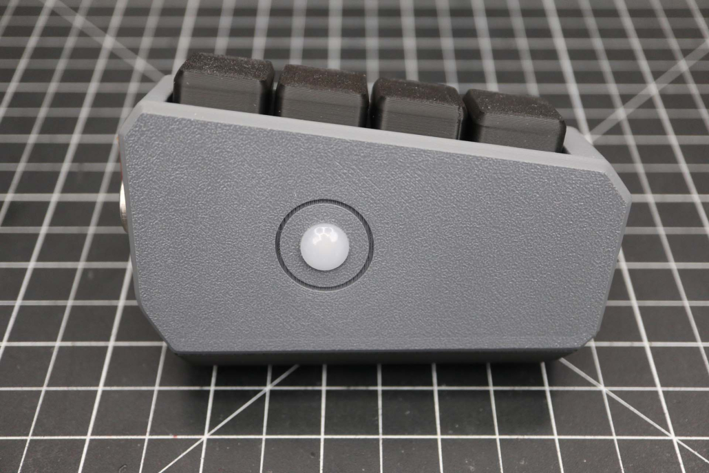
PARTS
- BlamconBuddy_Keycap_V1 OR MX Keycaps
STEPS
- Press the Keycaps into place
- All done! If you have not loaded the firmware in yet go to Blamcon.com/firmware and download the latest buddy firmware. When you plug your buddy in turn it on and it should connect like a USB drive, drop the firmware into that drive and have fun!