
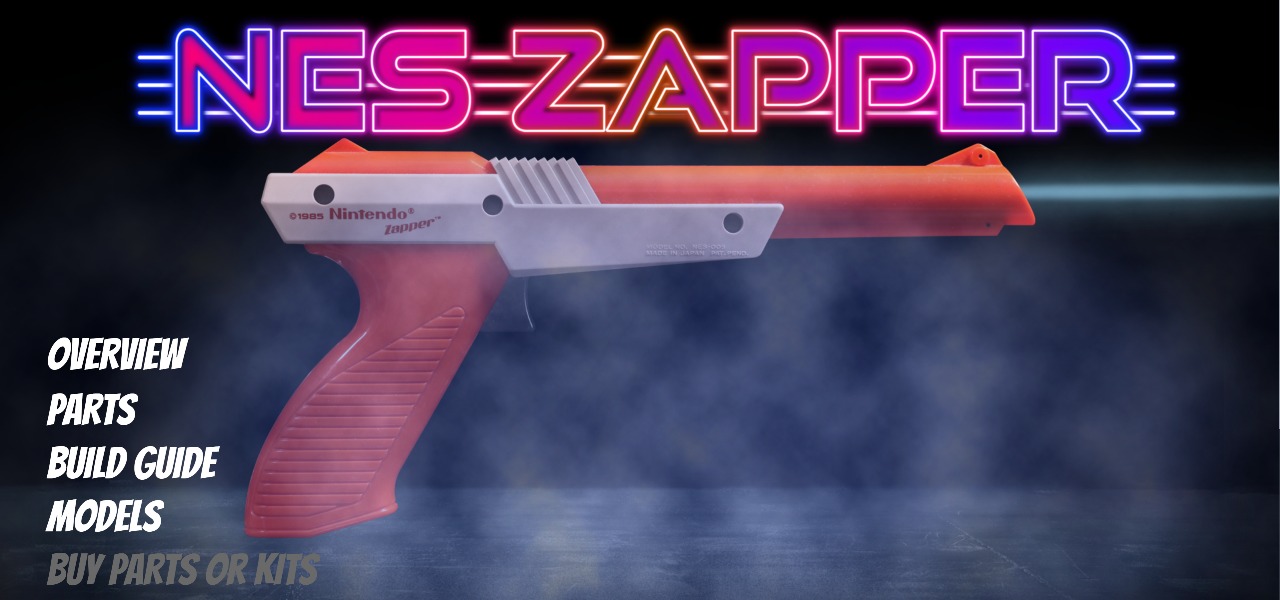



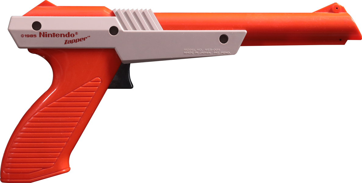


System: Nintendo NES
Year: 1985
Features: Click reset trigger (moddable), A/B buttons, LED, rumble
This is my most loved light gun and the epitome of classic light gun design. I’ve modded the trigger for a direct microswitch action. I added an A/B button to the side and an LED on back with a rumble inside. This light gun does not use a Blamcon core, just a Pico W, so the rumble needs to be a self-contained rumble module.
NOTE: In the video I mention about 2 trigger actions, the original and modded direct microswitch. The original trigger was designed for an old analogue system and can be sub 5ms in total actuation time (human response time is 250ms). This low of a response time can cause issues in some emulators and computers as this is not in line with modern systems. So the trigger mod is REQUIRED for now, we may find a solution in the future but for now please mod your triggers as per instruction.
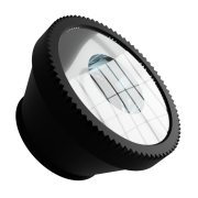
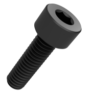
Wire Lengths
1 Drill the Button Holes
PARTS
- NES Zapper
STEPS
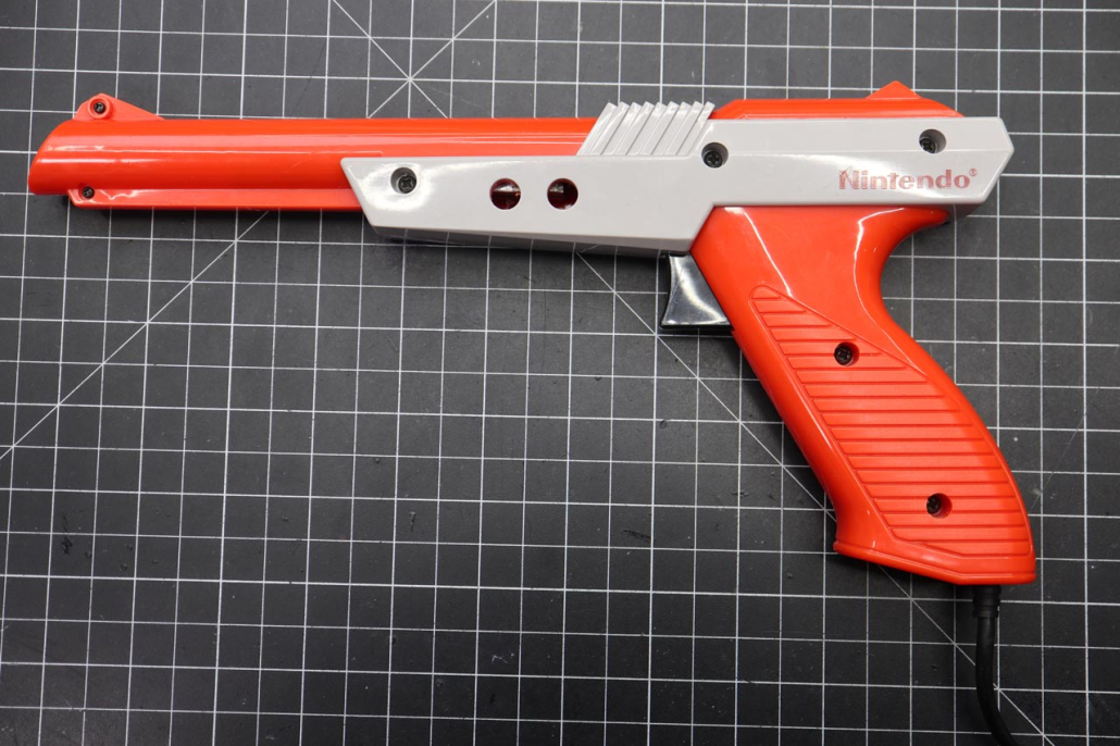
- Measure 47mm back from the gray side piece and 11mm down and mark, this is the A button hole location
- Measure 17mm back from the A button mark, also 11mm down, and mark. This is the B button hole
- Drill the A and B buttons through both sides of the frame, be careful not to go through the other side!
2 Drill the LED Hole
STEPS
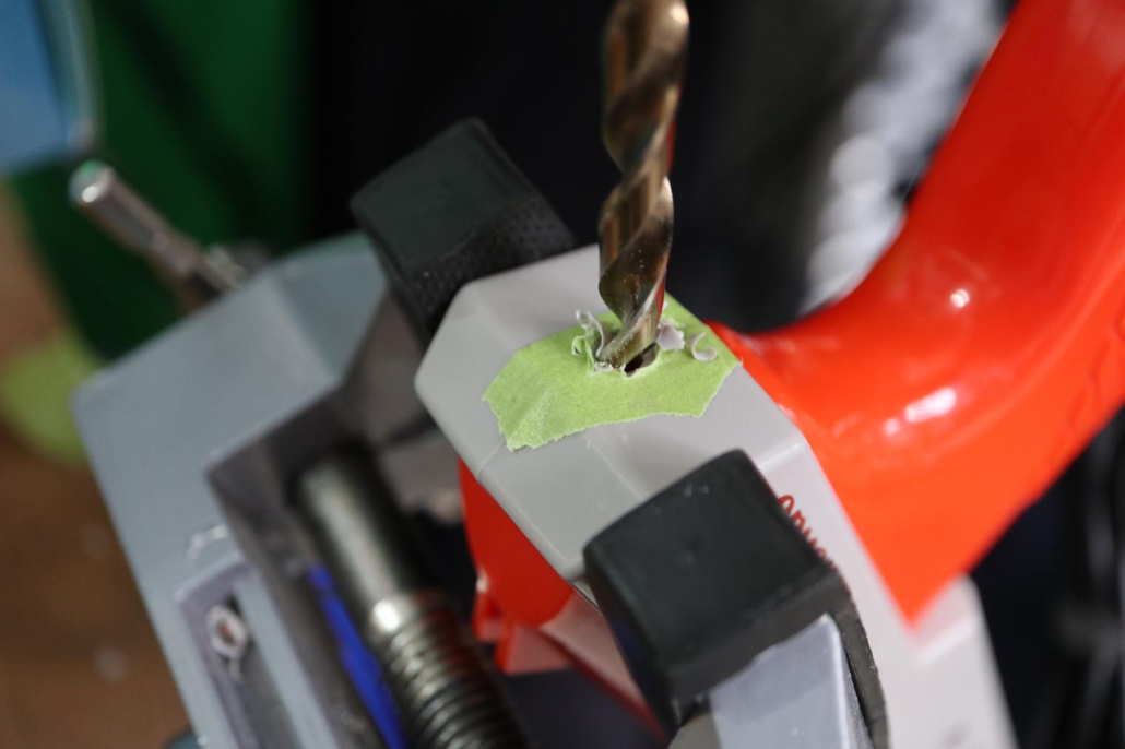
- Measure from the middle of the back and make a mark with an awl
- Drill through both layers in the back with a 6.5mm drill bit
Hint: You can heat the Awl to melt a bigger hole in the plastic
3 Take it Apart
STEPS
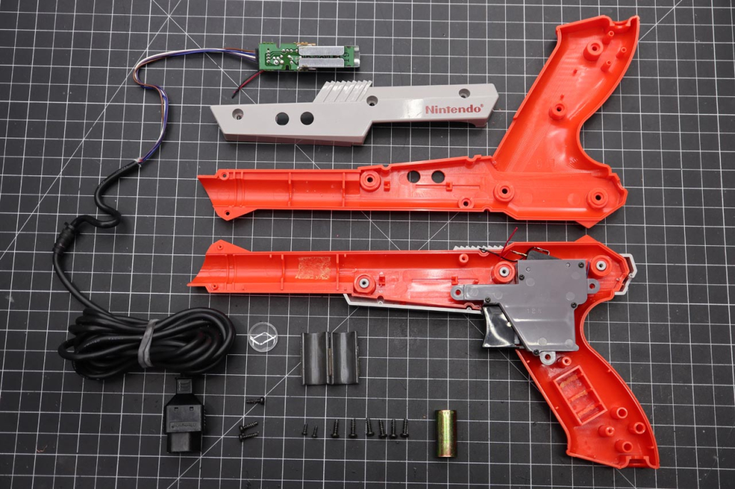
- Remove all screws in the frame and take the two halves apart
- Remove the frame gray side panels, there will be another screw hidden under
- Separate the two halves of the frame
- Discard the electronics except for the trigger
4 Trim The Back for the LED
STEPS
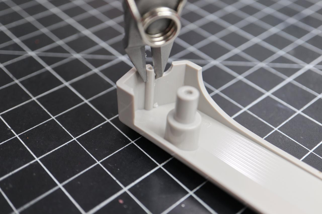
- The back of the frame cover flush around the LED hole on both sides
5 Prepare the Barrel
STEPS
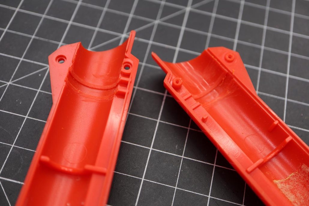
- Remove the lens
- Using a knife or Dremel remove the two ribs from the barrel that held the lens in place on both sides until flush
- One of the screw holes protrudes into the frame, trim it flush
6 Trim the Pico Mounting
STEPS
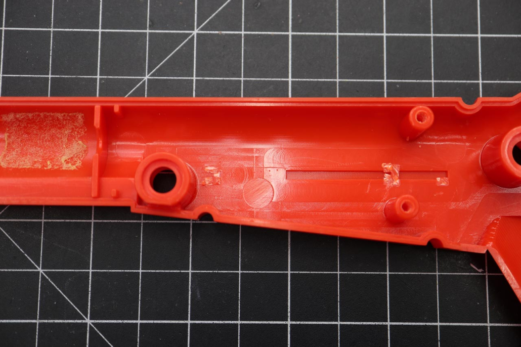
- a
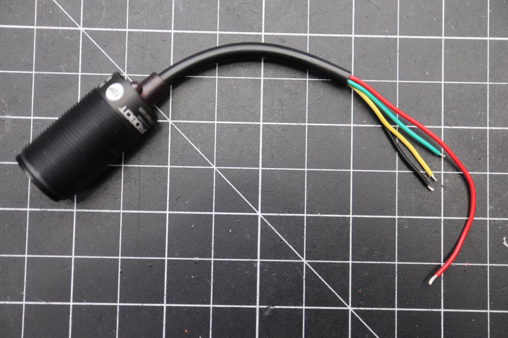
7 Prepare the Camera
PARTS
- SEN0158 Positional Camera
- Lens Adapter (optional)
STEPS
- Take the nuts off the camera and discard
- Cut the camera cable off at 140mm from the back, starting from the cone where the camera cable goes into the camera body, not the base
- Strip the thick insulation off the wires 50cm from the back cone, exposing the 4 inner wires
- The red wire stays the same length with 90mm exposed from the insulation
- Cut the Green, Yellow, and Black wires to 95mm from the base of the insulation so they are 45mm shorter than the red wire
- (Optional) Screw the lens adapter on as far as it will go, don’t force, then back it off a bit until the LED faces the left side of the gun, this is where it’s aligned. You will have to fine tune it later but this is a good place to start
- (Optional) Screw the wide angle lens on until it’s flush against the lens, do not force.
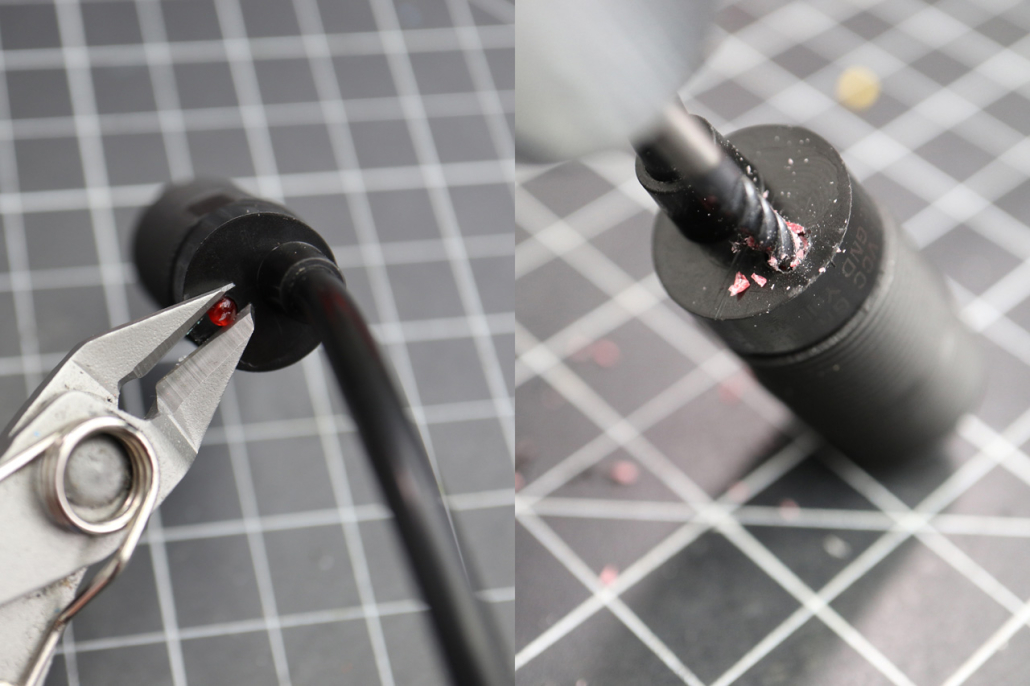
8 Remove the Camera LED (Optional)
PARTS
- SEN0158 Positional Camera
STEPS
- Clip the top off the camera LED to make it flush
- Use a small awl if needed to make an indent in the center of the LED to make it easier to drill
- Drill about 5mm down with a 3mm (1/8in) drill bit to cut the internal wire inside the LED resin casing
- Do NOT overdrill! You can do this after soldering the camera to the Pico so you can plug it into a USB power source as you go to check. When the light stops emitting, it’s done.
Note: A hand drill is recommended for this for obvious reasons
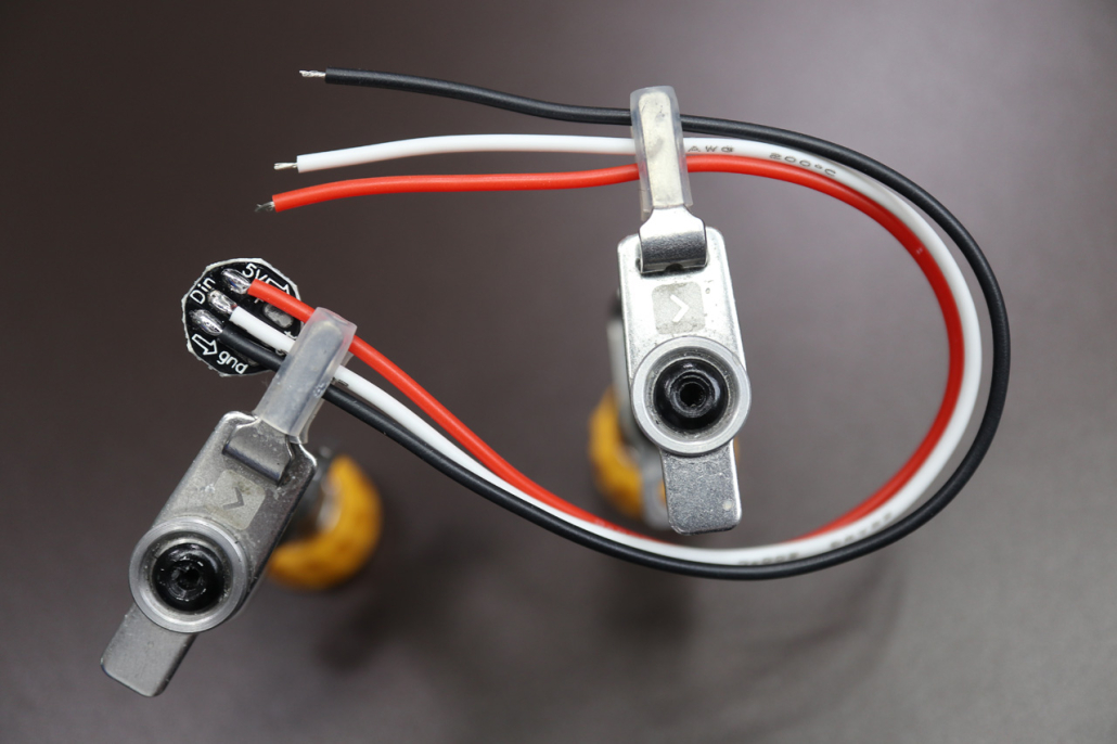
9 Solder the LED
PARTS
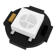
- NeoPixel LED
- 150mm Red/Black/White wires
STEPS
- Solder the wires to the ‘Din’ pads of the LED
- Red to positive (5V)
- White center (Din)
- Black to negative (Gnd)
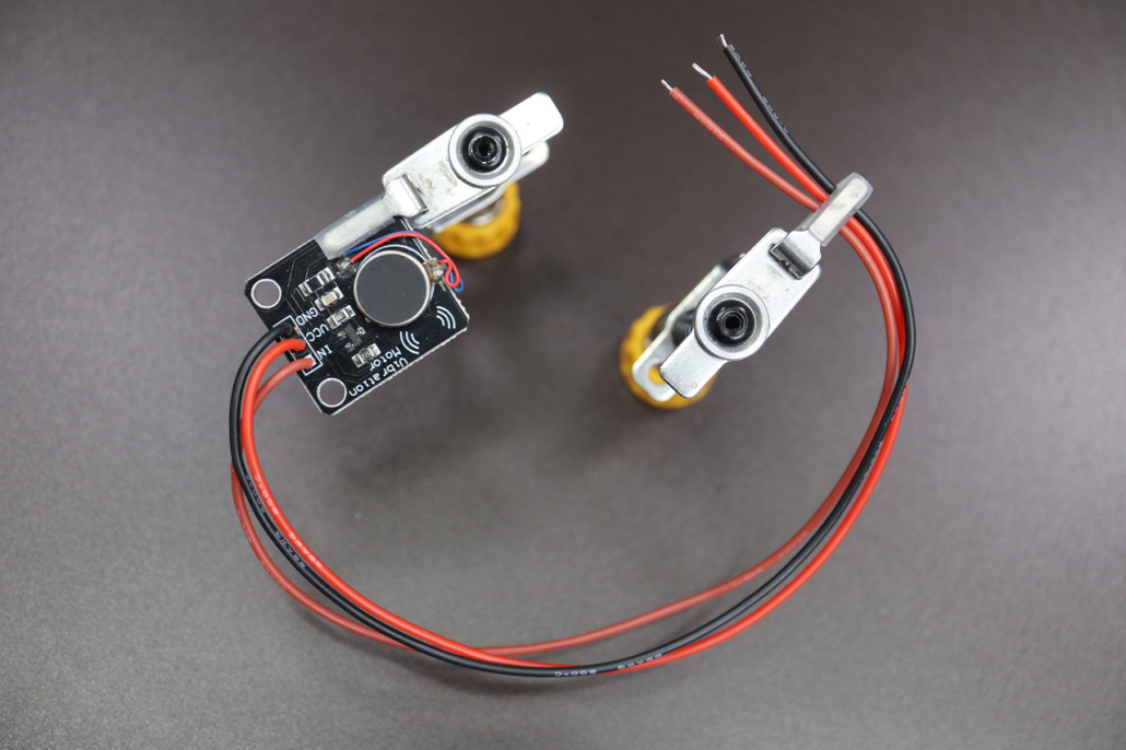
10 Solder the Rumble
PARTS
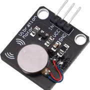
- Arduino Rumble Module
- 195mm Red/Black/Brown wires
STEPS
- Solder the brown wire to ‘In’
- Solder the red wire to ‘VCC’
- Solder the black wire to ‘GND’
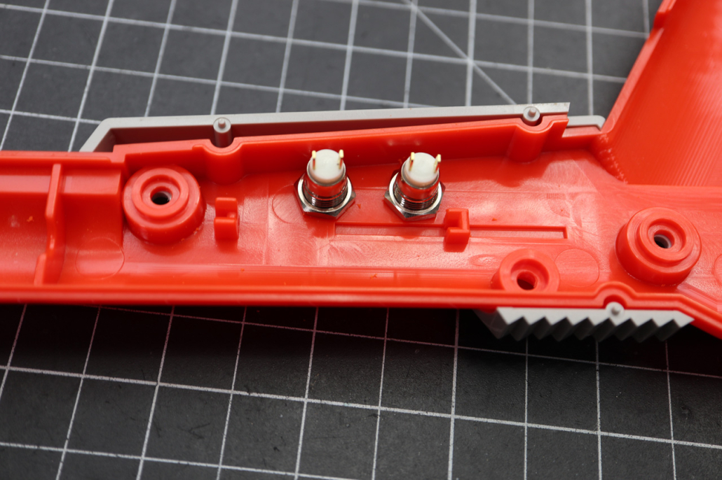
11 Install the A and B Buttons
PARTS
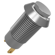
- 8mm Buttons X2
STEPS
- Screw each button in tightly by holding the nut in place and rotating the button until it’s snug
- (optional) Use a drop of hot glue or Loctite to keep the button from working loose over time. You don’t need a lot of glue
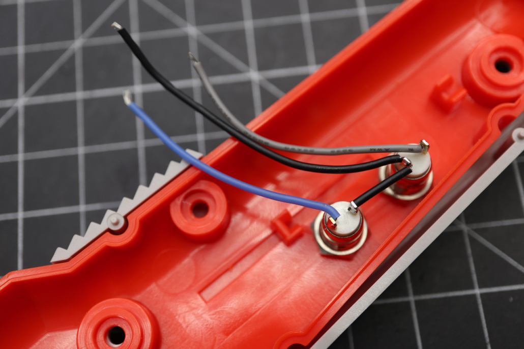
12 Solder A and B Buttons
PARTS
- Gray/Blue 50mm Wire
- Black 75mm wire
STEPS
- Solder the gray to one of the A button poles (front button)
- Solder the blue to one of the B button poles (back button)
- Solder the black to the second B button pole, then mark the wire and pull the insulation where it comes to the second A button pole and solder, this shares the ground wire between the A and B buttons
Note: Do NOT apply too much heat for a long time to these buttons, they have plastic inside and too much heat can ruin them
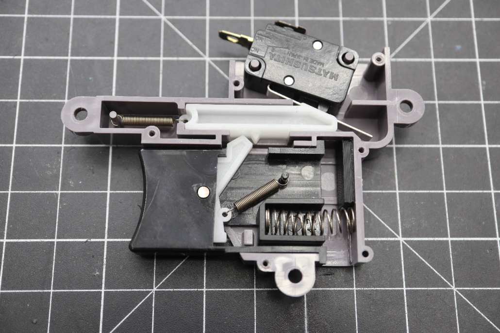
13 OPTIONAL: Mod the Trigger
If you want a more traditional trigger for better response this is an easy non-destructive modification to the trigger group to prevent the ‘click’ that releases the trigger.
PARTS
- NES_Zapper_Mod
STEPS
- Remove the screws from the trigger group and separate the two halves.
- Glue or double sided tape NES_Zapper_Mod in the location shown
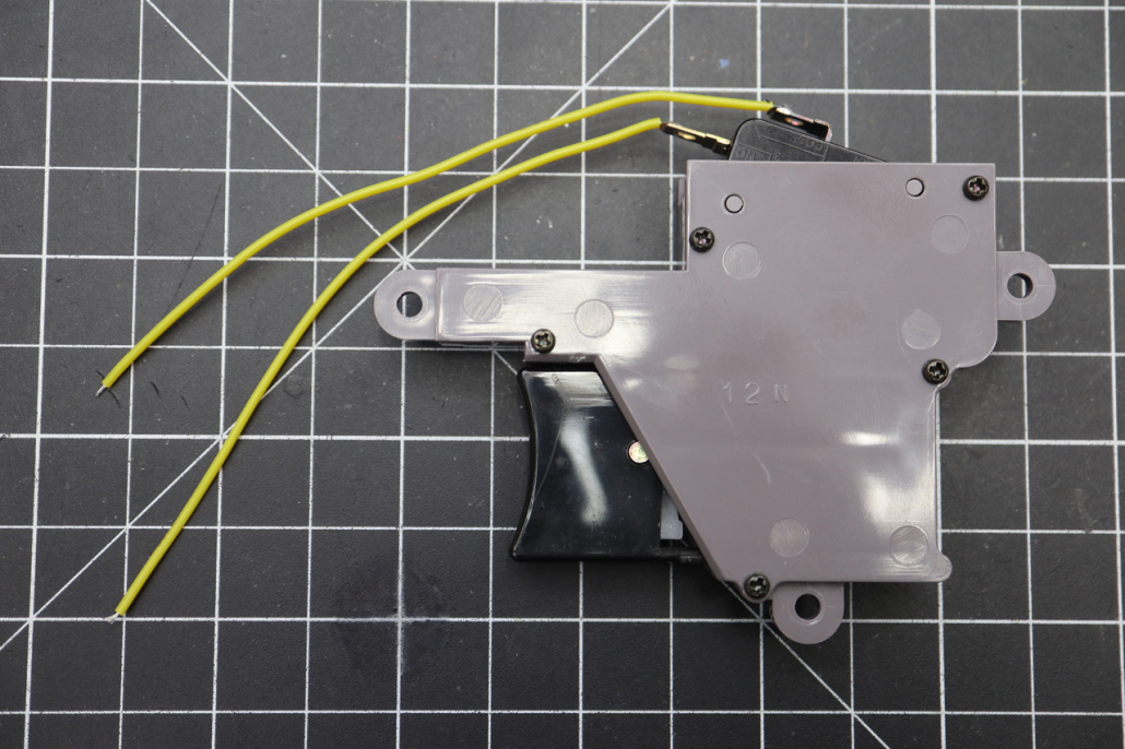
14 Solder the Trigger
PARTS
- 110mm Yellow Wire
- 100mm Black Wire
STEPS
- Desolder the wires on the trigger if still present
- Solder the yellow wire to the lower pole
- Solder the black wire to the top pole
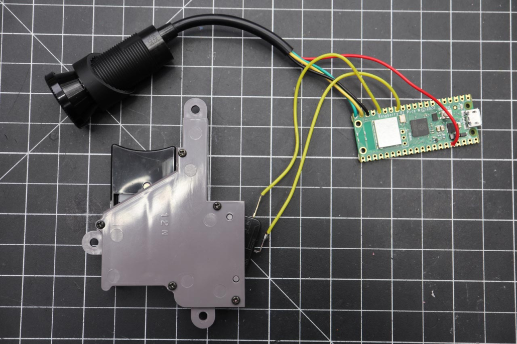
15 Solder the Camera and Trigger to the Pico
PARTS
- Presoldered Camera
- Presoldered Trigger
- Pi Pico W
STEPS
- Solder the camera 3.3V power (red) wire to Pin 36 of the Pico
- Solder the camera yellow wire to Pin 19
- Solder the camera green wire to Pin 20
- Solder the camera ground (black) wire to Pin 18
- Solder the trigger signal wire (yellow) to Pin 16
- Solder the trigger ground wire (black) to Pin 13
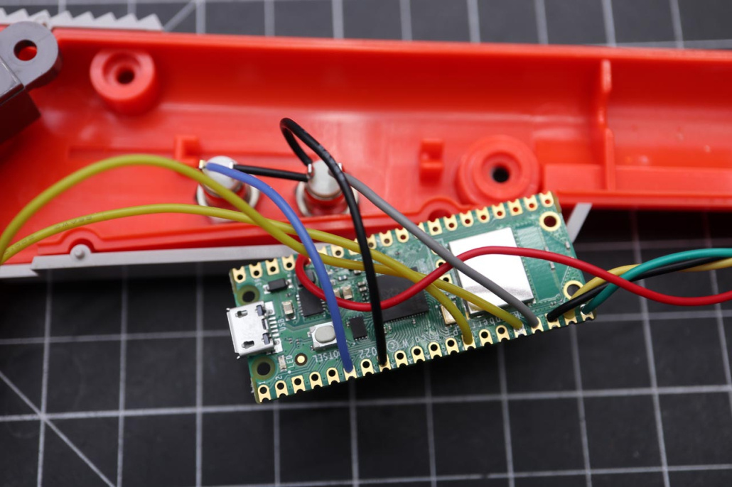
16 Solder the A and B Buttons to the Pico
PARTS
- Presoldered A+B Buttons
STEPS
- Solder the A Button signal wire (Gray) to Pin 17
- Solder the B Button signal wire (Blue) to Pin 6
- Solder the shared A/B ground wire (Black) to Pin 8
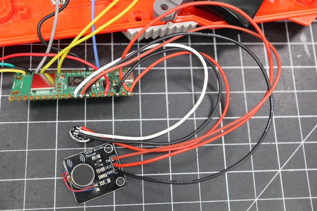
17 Solder the Rumble and Neopixel to the Pico
PARTS
- Presoldered Neopixel LED
- Presoldered Arduino Rumble Module
STEPS
- Solder the 5V red wire of the RGB LED AND rumble to Pin 40 of the Pico
- Solder the rumble In (brown) wire to Pin 32
- Solder the Neopixel Din wire to Pin 31
- Solder the rumble ground wire (GND) to Pin 33
- Solder the Neopixel Ground wire (Gnd) to Pin 38
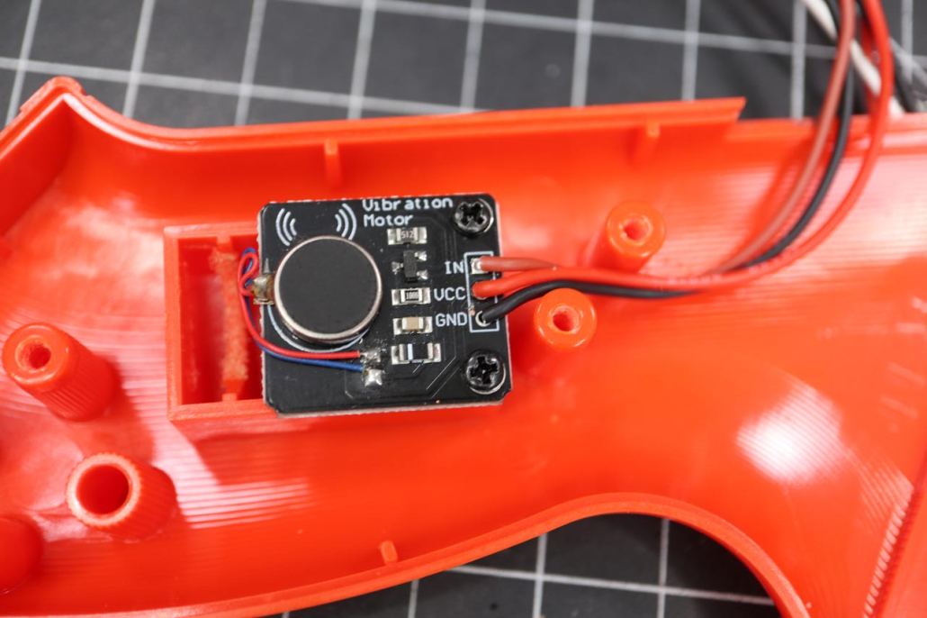
18 Install the Rumble
PARTS
- Pan head 2.5mm X 6mm screws
- NES_Zapper_RumbleHolder
STEPS
- Insert NES_Zapper_RumbleHolder into the weight holder in the frame, secure with superglue or hot glue. Remove the foam from the holder if present
- Screw the rumble into the holder with the 2.5mm Cap Head screws
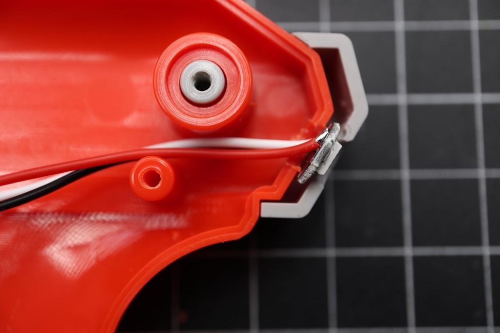
19 Install the Neopixel LED
PARTS
- Presoldered NeoPixel LED
STEPS
- Insert the left half of the frame cover back on
- Insert the LED between the frame cover and the frame, aligning the LED with the hole on the frame cover and making sure the wires go through the hole in the frame
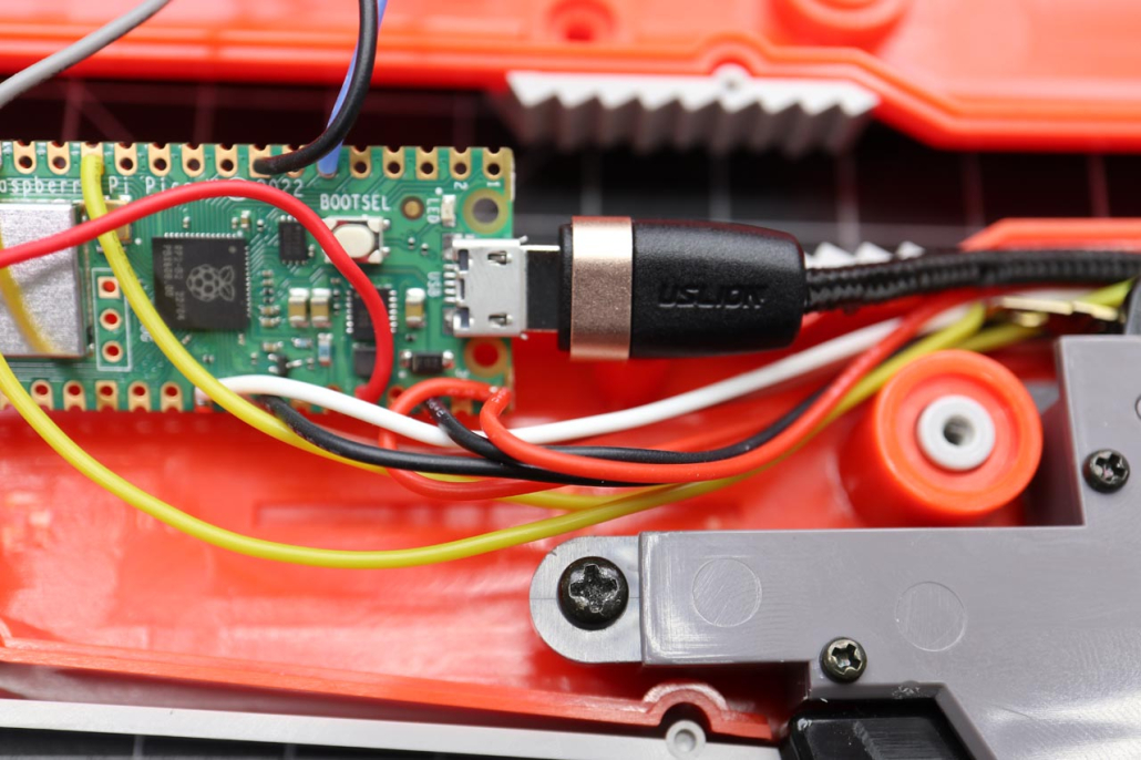
20 Plug in the USB Cable
PARTS
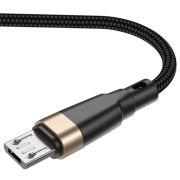
- USB Cable
STEPS
- Plug in the USB cable, make sure the connector isn’t longer than 12mm from the port, if it’s longer trim off the cable protector until it fits while the pico is laying flat in the frame (see step 23 for how it should look in place)
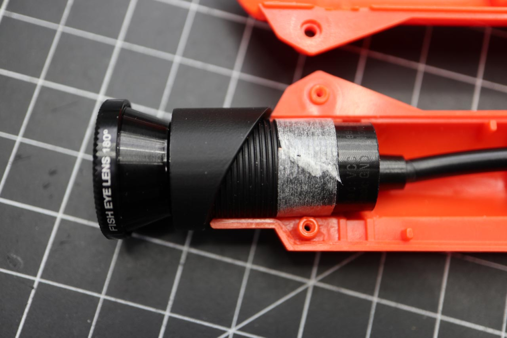
21 Install the Camera
This can be done with or without the wide angle lens
WIDE ANGLE INSTALL STEPS (Optional)
- Screw the wide angle lens on the camera as far as it will go, do not overtighten!
- Back the lens adapter off enough that the camera wire is on the right side, this is the correct alignment
- Screw the wide angle lens on until it is touching the camera filter.
STEPS
- If you want, add a bit of double sided tape to keep the camera from moving, this helps but it should be tight enough when screwed together it won’t matter
- Align the camera so the cable is facing to the right at 90deg, this is the correct alignment for the camera, we’ll fine tune it later
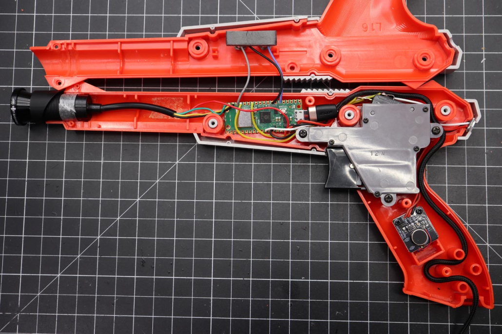
22 Route the Wires
STEPS
- Take a look at the image and route the wires as shown
- If needed you can bend the terminals of the trigger switch down a little, running the wires behind the terminals makes it easier to put together
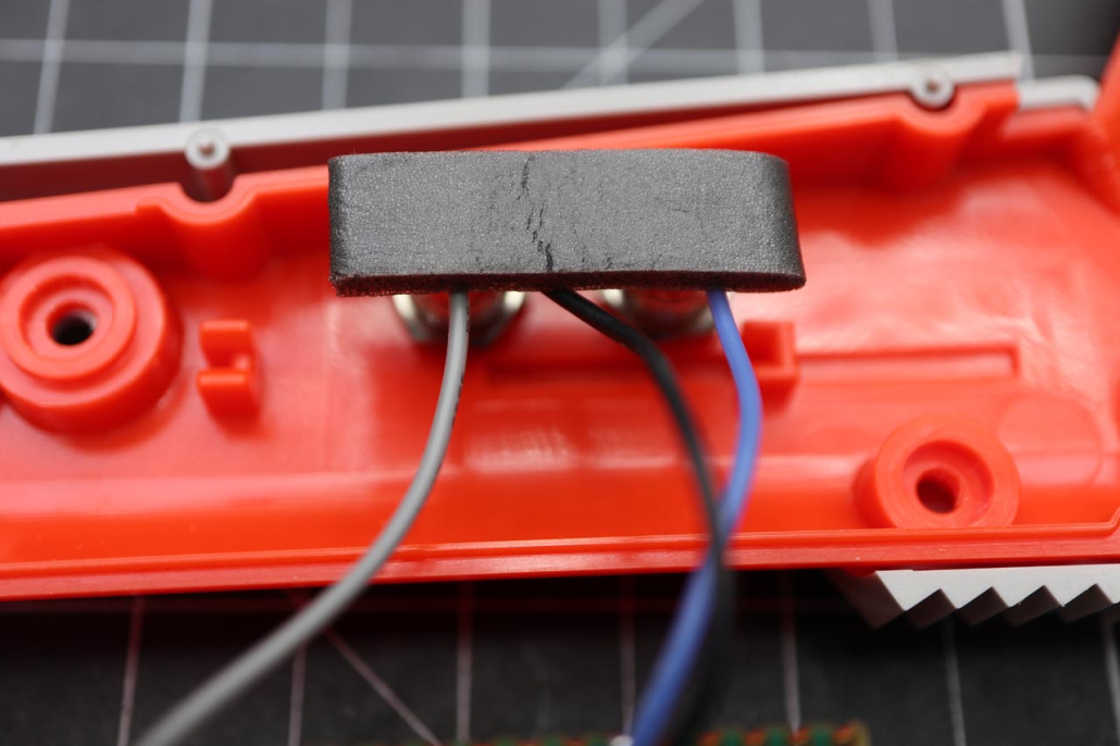
23 Cover the Button Terminals
PARTS
- Tape, preferably foam tape but even masking tape is fine
STEPS
- Place a piece of tape on the back of the wire terminals, there’s a chance for the terminals to touch something on the Pico they shouldn’t so this helps ensure that doesn’t happen.
24 Align the Camera
STEPS
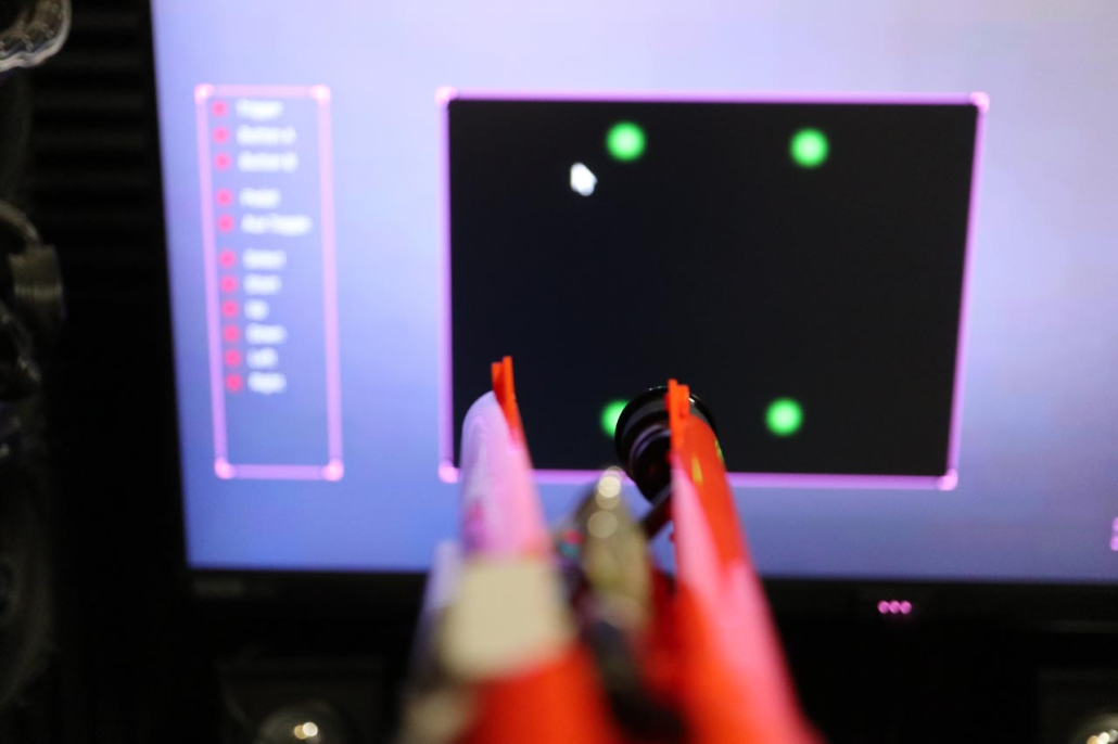
- Holding the two haves together with the camera correctly positioned in the right side, held by double tape. Follow the guide here to align the camera: https://www.youtube.com/watch?v=QJ2YZrbyOsE&t=4017s
- Once aligned carefully put the two halves together and lay it down ready to screw together, if any wires get caught check the wire routing in step 21
25 Screw it Together and Have Fun!
STEPS
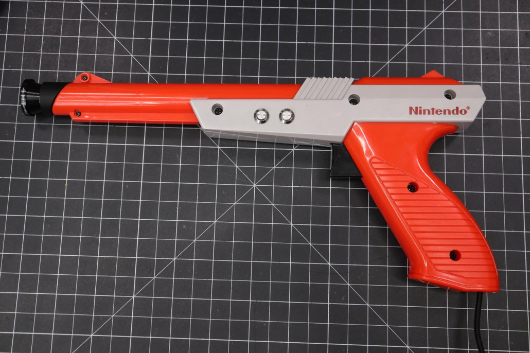
- Screw the 5 larger screws into the body and grip, you will have one left over because it can’t be screws in with the buttons in place, it won’t affect anything
- Screw the two smaller screws into the front
- Start playing some games!