
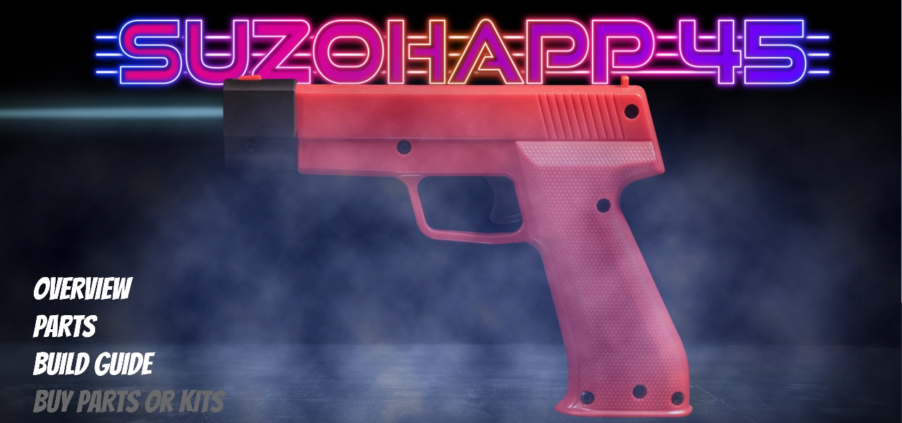



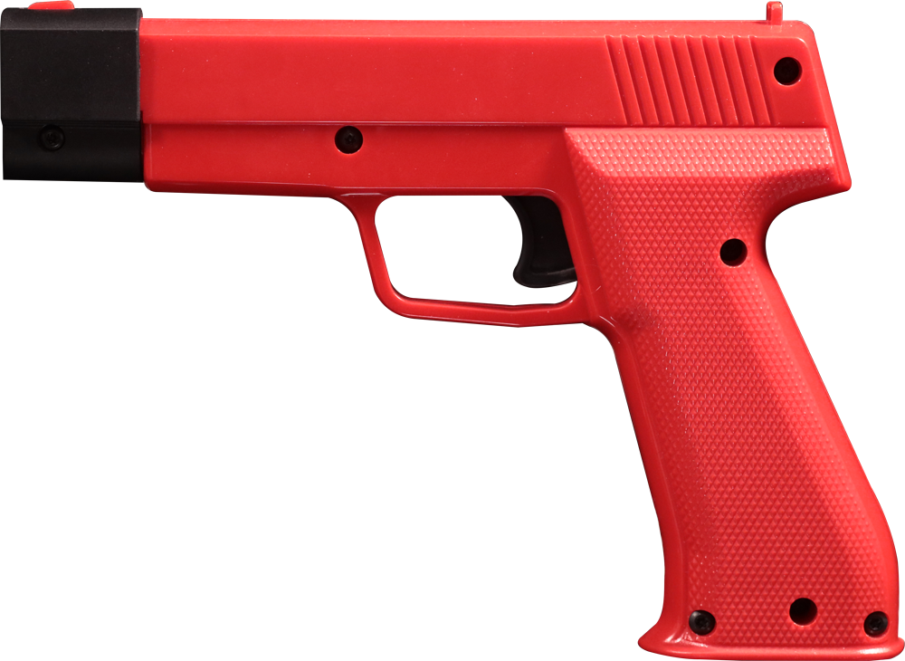


About the SuzoHapp45 Arcade Gun
The Suzohapp 45 is a currently in production light gun so you can get this relatively affordably new. It is an easy conversion to Blamcon with very few steps, the biggest skill you will need for this one is the drilling. This is the only conversion so far that doesn’t need any 3D printing.
The gun features recoil, rumble, A/B button and microswitch trigger. The cable is integrated and not separate as there’s not enough space for a GX-16 on the bottom.
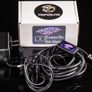
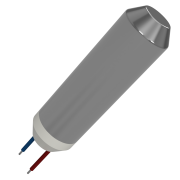
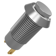
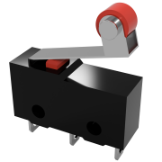
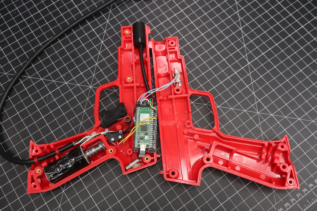
Complete And Open
- Direct cable for computer, 6 pin with 4 for USB, 2 for 24V
- A and B button on left side, 8mm holes drilled to mount, ground wire shared
- Original long roller microswitch
- Rumble mounted in the back, hot glued
- Original solenoid, anything that fits can be swapped
- Core is loose in the front of the frame, it stays very well just with the wires and doesn’t rattle at all, you can tack it in with hot glue if you like
- For core wiring please refer to the next image
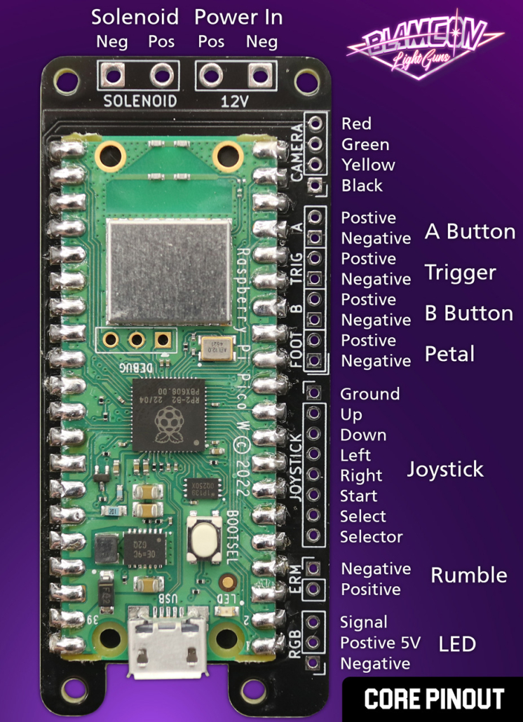
Core Wiring
- When wiring the core please refer to this pinout diagram
Wire Lengths
Camera – Trimmed to 110mm from base
Trigger – 60mm X2
A button – 100mm
B button – 100mm
AB button shared ground – 115mm
Rumble – 40mm (attached)
Solenoid – Trimmed to 130mm from base
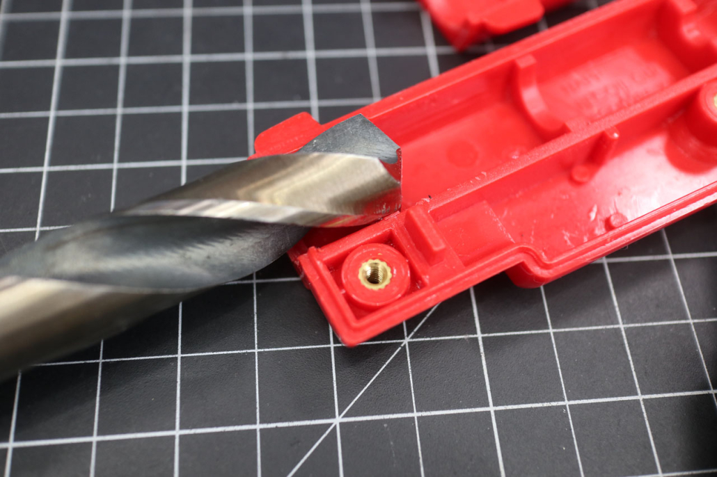
Camera
- Use an 18MM drill bit to carefully and slowly open up the front to fit the camera, go slow, back it up. The plastic is strong but it’s still plastic
- Camera should sit snug and screws should hold it in place, if not add thin double tape to the camera until the screws clamp it firmly
- You can put the Blamcon wide angle lens adapter on the end before mounting the camera for closer play
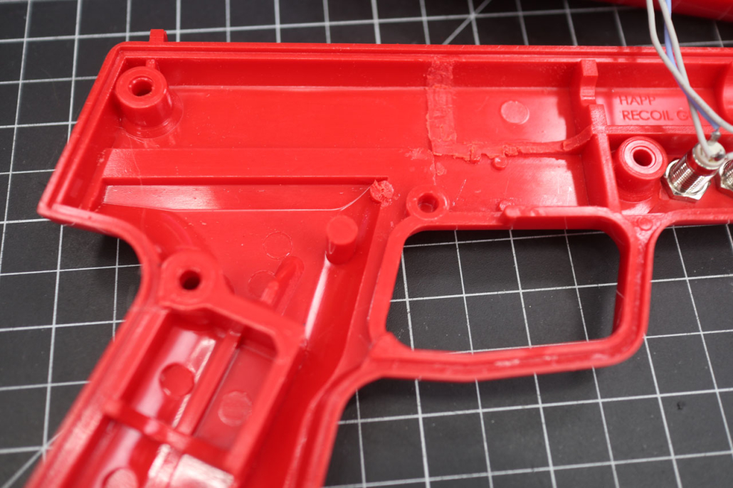
Mod the Left Half
- Using a Dremel or equivalent, remove the part of the frame as shown
- Do NOT remove the small pin shown, I’ll replace that image, that’s for the trigger spring, things happen. It doesn’t affect function 😀
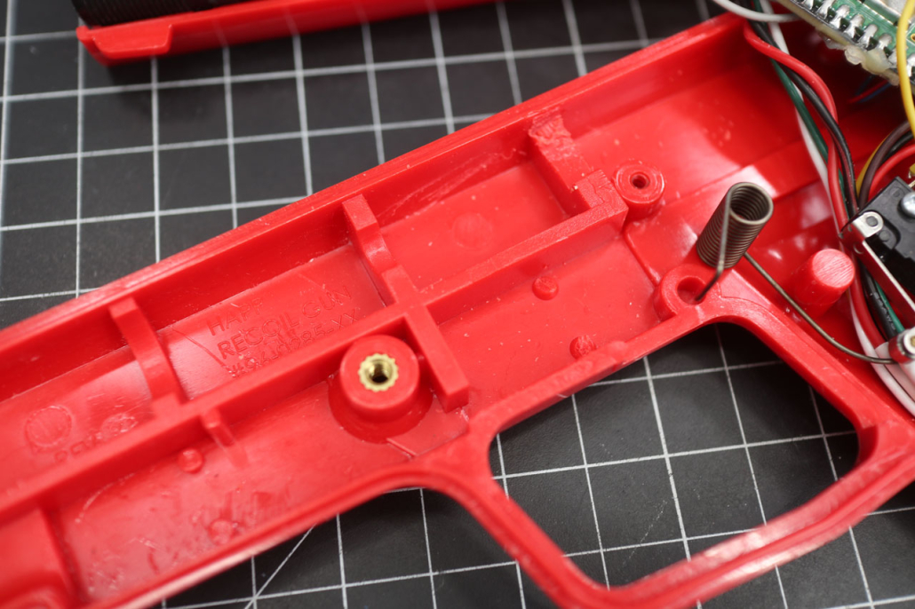
Trigger and Rumble
- Using a Dremel or equivalent, remove the part of the frame as shown
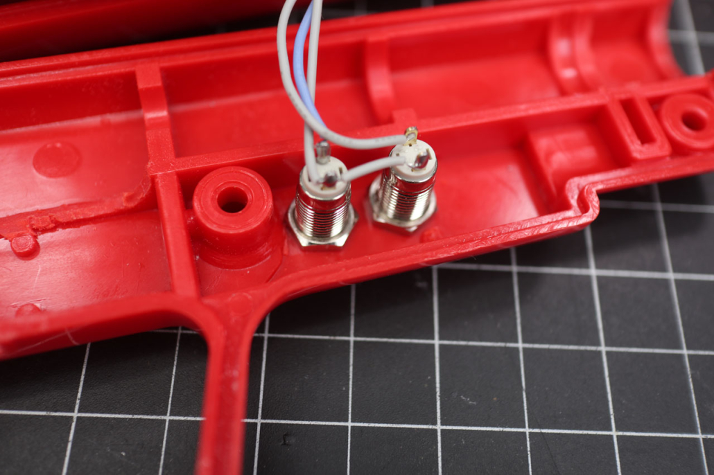
A and B buttons
- Drill holes on the locations shown for the 8mm buttons
- Solder a 100mm wire to the A button
- Solder a 100mm wire to the B button
- Solder a 115mm wire to the A then strip a bit and wire it to the B, solder that to the A or B ground pin on the core.
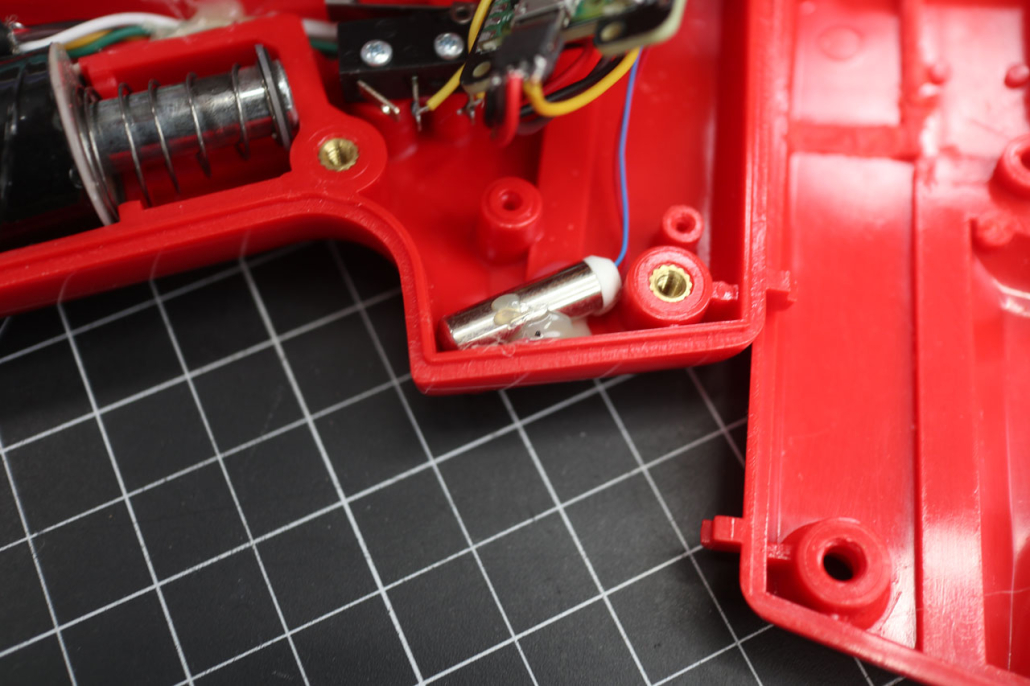
Attach the Rumble
- Trim the rumble wire to around 40mm
- Hot glue the rumble to the frame. I put it here but it doesn’t matter where really.
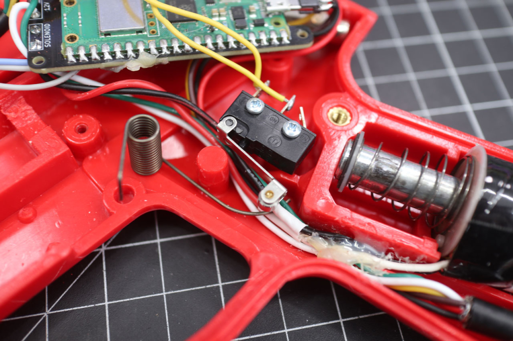
Trigger and Cable Wiring
- Run the wires under the trigger as shown. If you’re using a cable strip it high enough that it’s only the smaller wires
- Tack the wires in place, if they don’t move they won’t get into the trigger, ever
- Screw the roller microswitch in as shown and make sure it doesn’t get caught in the wires
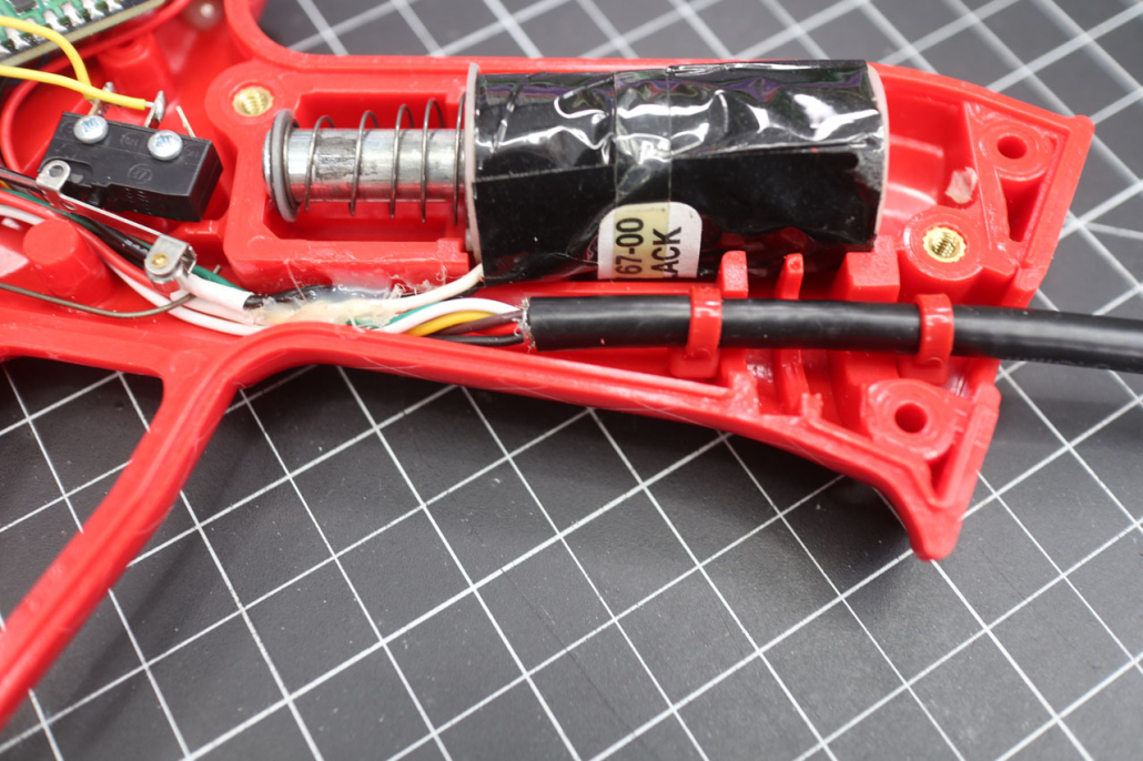
Attach the Cable
- I would highly recommend attaching zap straps as shown, this lets the cable rotate freely but not move up and down. This keeps it all secure and prevents the cable from getting ‘yoinked’ on the thinner wires
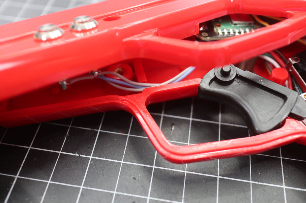
Attach the Cable
- Pretty much all the wires can be just be moved in place, except the button wires, they need to be routed through this little gap at the bottom to make sure they don’t get pinched.
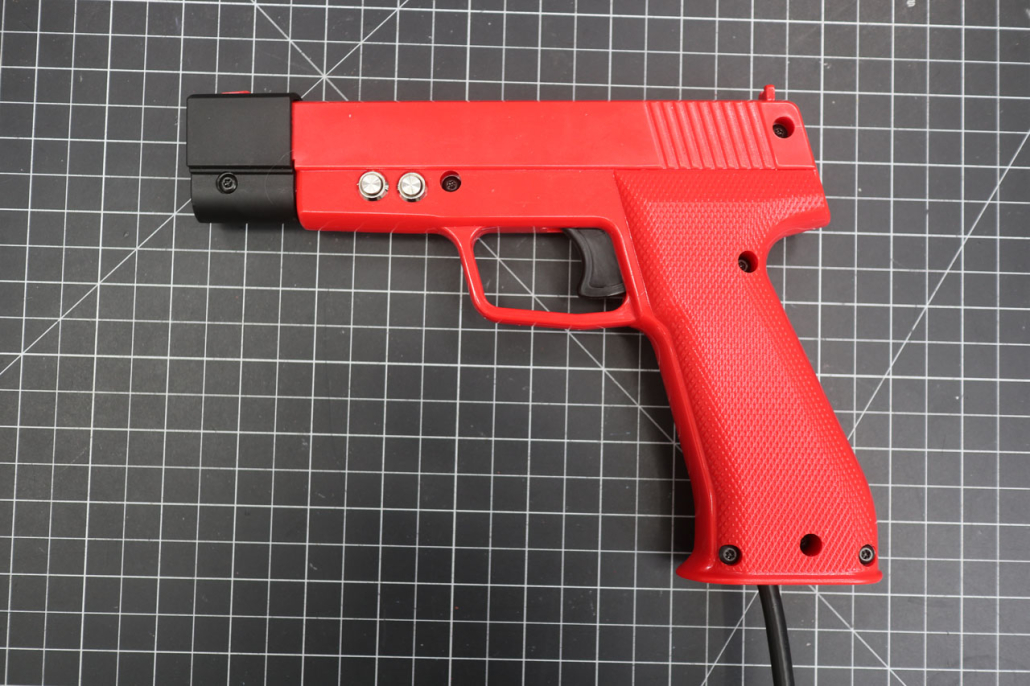
All Buttoned Up
- Make sure everything is cinched up and no wires are caught before screwing it together