




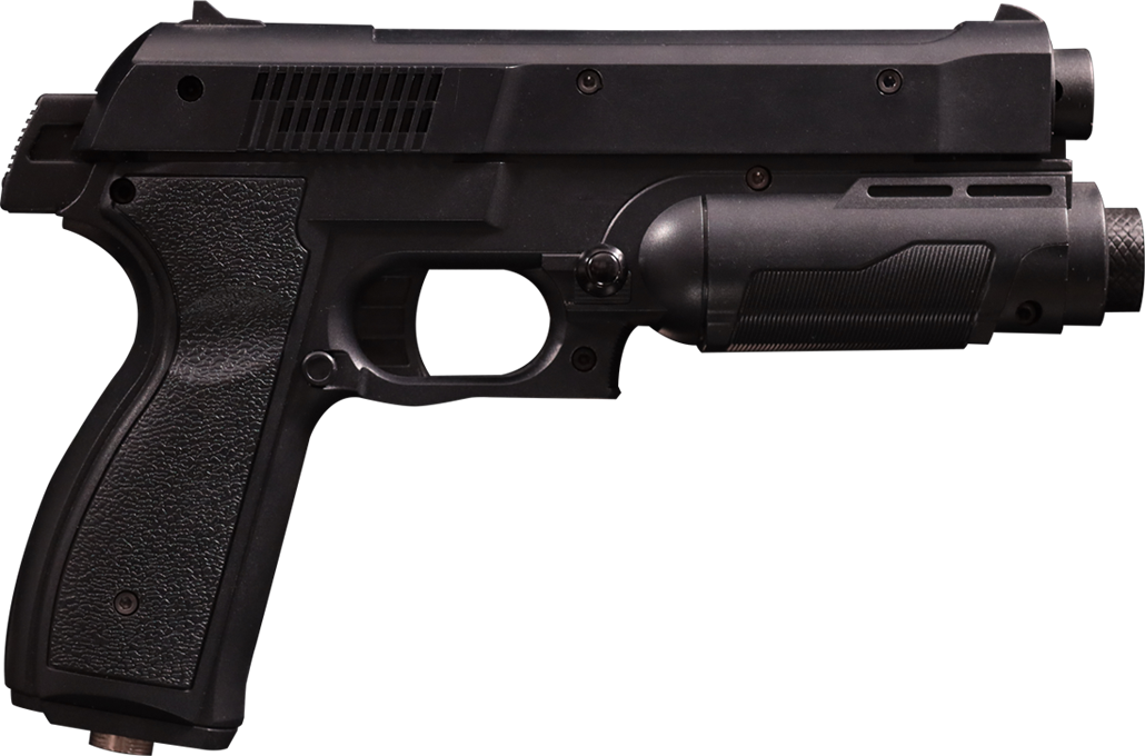


About the Time Crisis 4 Arcade Gun
The Time Crisis 4 Arcade Gun is one of the best choices to convert to a modern light gun. You can find them new with recoil on sites like Ebay and Aliexpress and the conversion is very easy. The conversion only needs one file to hold the camera and slots right in. The shells you can buy aren’t cheap, but they’re extremely high quality.
This light gun features a solenoid recoil that opens the bolt when fired, rumble motor, A and B button added on the sides, and an LED on the back. The trigger action is quite long but uses a satisfying roller microswitch when activated.
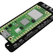
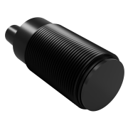
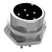
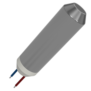
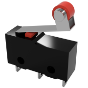
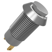
Wire Lengths
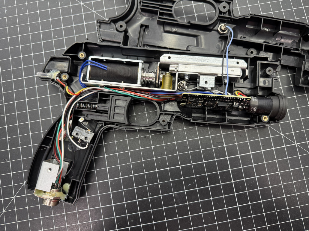
Complete And Open
- GX16 in the grip, mounted to the arcade cable attachment
A and B button on either side, mounted through 8mm holes - 4mm hole drilled into the hammer LED connected with 4mm fiber optic (optional) for visibility.
- Rumble mounted in the grip, hot glued
- Solenoid in bracket with plate attached
- Core is loose in the front of the frame, it stays very well just with the wires, you can tack it in with hot glue if you like
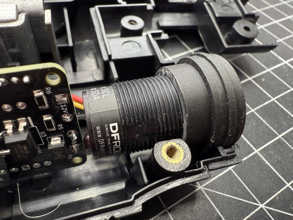
Camera
- If you want a lens screw on the lens adapter and lens now.
- Screw the camera into the 3D printed adapter, LED facing left until it’s flush with the adapter.
- Cut the camera cable off to 30mm and remove the outer insulation
- Carefully cut the wire guide off the back of the camera, I use flush cutters and slowly go around, do NOT cut the wires!!
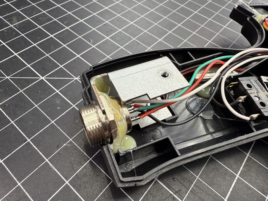
GX 16
- Solder the GX16 cable (1 12V Positive, 2 12V Negative, 3 USB Positive, 4 Data Positive, 5 Data Negative, 6 USB Negative)
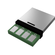
- Solder the USB connector (Left to Right: USB Positive, USB Data Negative, USB Data Positive, USB Negative)
- The GX16 should sit snug in the bracket, add a bit of hot glue to keep it from working loose.
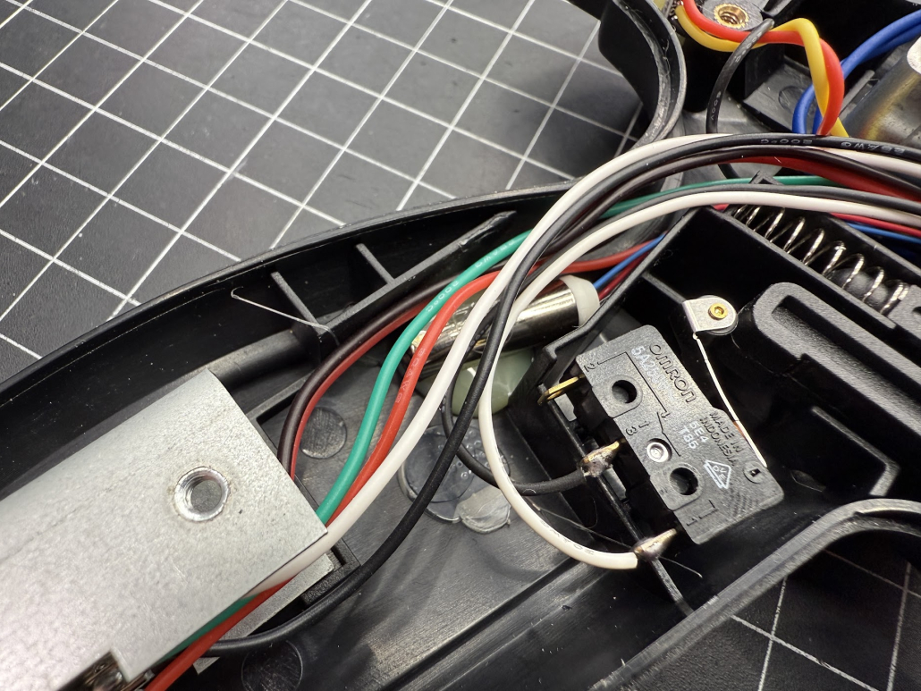
Trigger and Rumble
- Solder 220mm wires to the trigger, do not solder to the pin above the roller but the pin where the lever attaches and the middle pin.
- Cut the rumble motor wires to 160mm or extend to 160mm if too short.
- Hot glue the rumble in the position shown.
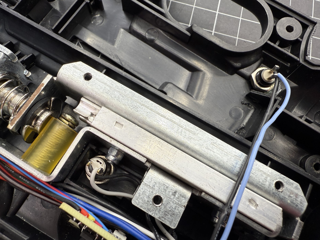
A and B buttons
- Drill holes on the locations shown for the 8mm buttons
- Solder 2 60mm wires to the A button
- Solder 2 80mm wires to the B button
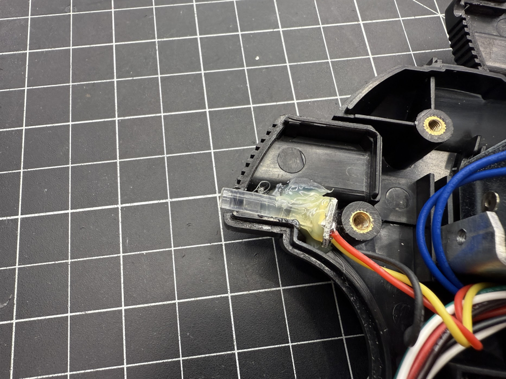
Attach the LED
- Hot glue a 4mm fiber optic cable to the face of the LED
- Solder the three 150m LED wires to the input of the neopixel LED (arrow in and marked with Din on the data pin)
- Solder to the core in this order: Black (square), positive, Din
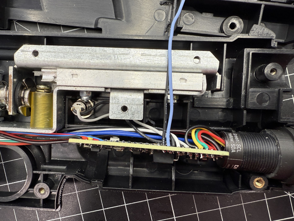
Mount the Core
- The core can sit loose at this angle
- Solder the component buttons to the core using the markers on the core, ground wires go into the square holes
- Plug in the USB cable and solder the 12V power wires to the 12V holes on the core